Indirect evaporation fluid cooling device with built-in heat exchanger
A fluid cooling and evaporative cooling technology, which is applied in the application field of the central air-conditioning system, can solve the problems of low cooling capacity and low cooling efficiency, and achieve the effect of improving cooling capacity, water evaporation and overall evaporative cooling efficiency
- Summary
- Abstract
- Description
- Claims
- Application Information
AI Technical Summary
Problems solved by technology
Method used
Image
Examples
no. 1 example
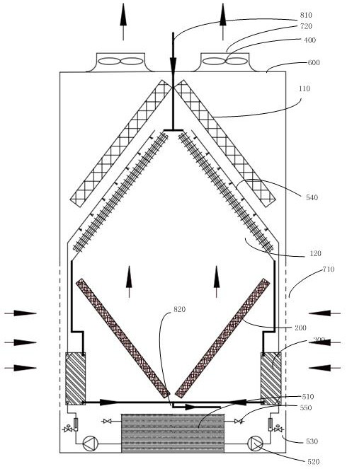
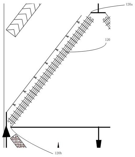
[0034] The indirect evaporative fluid cooling device of this embodiment, such as figure 1 As shown, it includes housing 600, air inlet 710, air outlet 720, fan 400, fluid inlet 810, water collection module 110, spray module 540, evaporative cooling heat exchanger 120, fluid outlet 820, wet film 200, heat exchanger 300 , a sump 510 , a circulating water pump 520 , and a replenishment valve 550 . From the perspective of external air, they are air inlet, wet film, evaporative cooling heat exchanger, spray module, water collection module, fan, and air outlet; from the perspective of circulating water, they are sump, circulating water pump, heat exchanger, and spray module , evaporative cooling heat exchanger, wet film, sump, and water replenishment valve; from the perspective of the cooled fluid, it is divided into fluid inlet, evaporative cooling heat exchanger, heat exchanger, and fluid outlet.
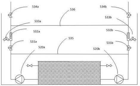
[0035] Preferably, an automatic filter sewage discharge device 530 is also provide...
Embodiment 2
[0058] Such as Figure 5 As shown, the difference between Embodiment 2 and Embodiment 1 is that an air-cooled surface cooler, an air-cooled circulation pump, and a check valve are further added after the cooled fluid flows out of the heat exchanger.
[0059] The air-cooled surface cooler 130 is arranged on the front side or below the air inlet direction of the wet film 200 , and the air-cooled surface cooler communicates with the air inlet 710 . The water outlet of the air-cooled surface cooler 130 is connected to the fluid inlet 810 of the indirect evaporative fluid cooling device through a pipeline; the water inlet of the air-cooled surface cooler 130 and the cooled fluid outlet of the heat exchanger 300 are connected to the air cooling cycle in sequence Pump 140, check valve 150.
[0060] When the fluid outlet temperature of the entire indirect evaporative fluid cooling device is lower than the ambient dry bulb temperature, the air-cooled surface cooler uses the cooled flu...
Embodiment 3
[0064] Embodiment three and embodiment four
[0065] Such as Figure 6 and Figure 7As shown, Embodiment 3 and Embodiment 4 further optimize the water eliminator into a fluid precooling surface cooler 110a on the basis of Example 1 and Embodiment 2, so as to collect water vapor and make full use of residual cooling in the air Cool the fluid to be cooled, improve the utilization rate of the residual air cooling of the cooling tower, and improve the cooling capacity of the indirect evaporative fluid cooling device.
[0066] Preferably, the surface of the fluid precooling surface cooler is provided with a hydrophilic coating added with infrared radiation heat dissipation material. In this embodiment, the coating contains nano-silicon dioxide or nano-alumina, and contains transition metal oxides such as cobalt, nickel, and manganese. Setting such a coating can improve the heat exchange efficiency of the fluid pre-cooling surface cooler, and at the same time better absorb water ...
PUM
 Abstract
Description
Claims
Application Information
 - R&D
- Intellectual Property
- Life Sciences
- Materials
- Tech Scout
- Unparalleled Data Quality
- Higher Quality Content
- 60% Fewer Hallucinations
Browse by: Latest US Patents, China's latest patents, Technical Efficacy Thesaurus, Application Domain, Technology Topic, Popular Technical Reports.
© 2025 PatSnap. All rights reserved.Legal|Privacy policy|Modern Slavery Act Transparency Statement|Sitemap|About US| Contact US: help@patsnap.com


