
Drilling sampling device for geological exploration

A technology of geological exploration and sampling device, which is applied in the direction of sampling device, etc., can solve the problems of difficulty in taking out samples, poor stability, increased staff burden, etc., and achieves the effect of improving stability and reasonable structure design.

Inactive Publication Date: 2021-11-19
刘晟辰
View PDF0 Cites 6 Cited by
  • Summary
  • Abstract
  • Description
  • Claims
  • Application Information

AI Technical Summary

Problems solved by technology

[0003] Drilling equipment is often used for sampling operations in geological exploration. Traditional drilling equipment has poor stability when using sampling cylinders to drill the ground, and the samples in the sampling box are difficult to take out after being squeezed, which increases the burden on the staff. , for this purpose, we propose a drilling sampling device for geological exploration

Method used


Image

  • Drilling sampling device for geological exploration
  • Drilling sampling device for geological exploration
  • Drilling sampling device for geological exploration

Examples


Embodiment 1

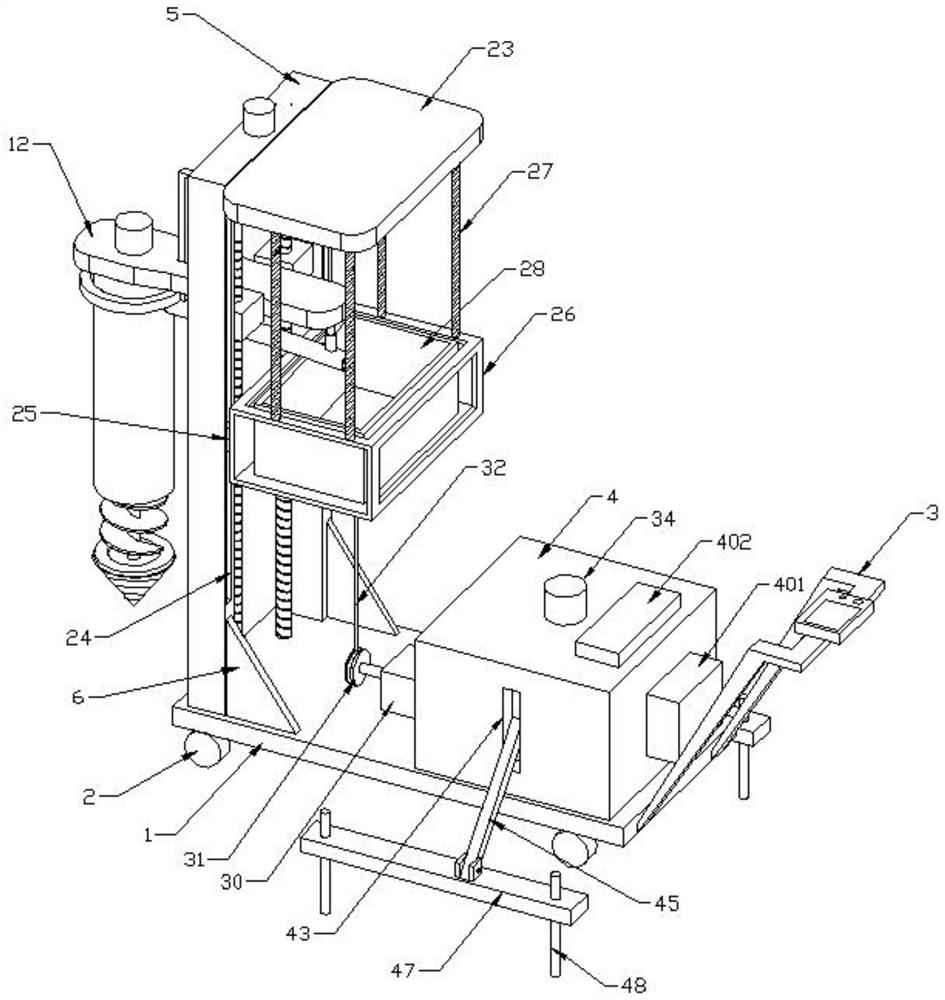
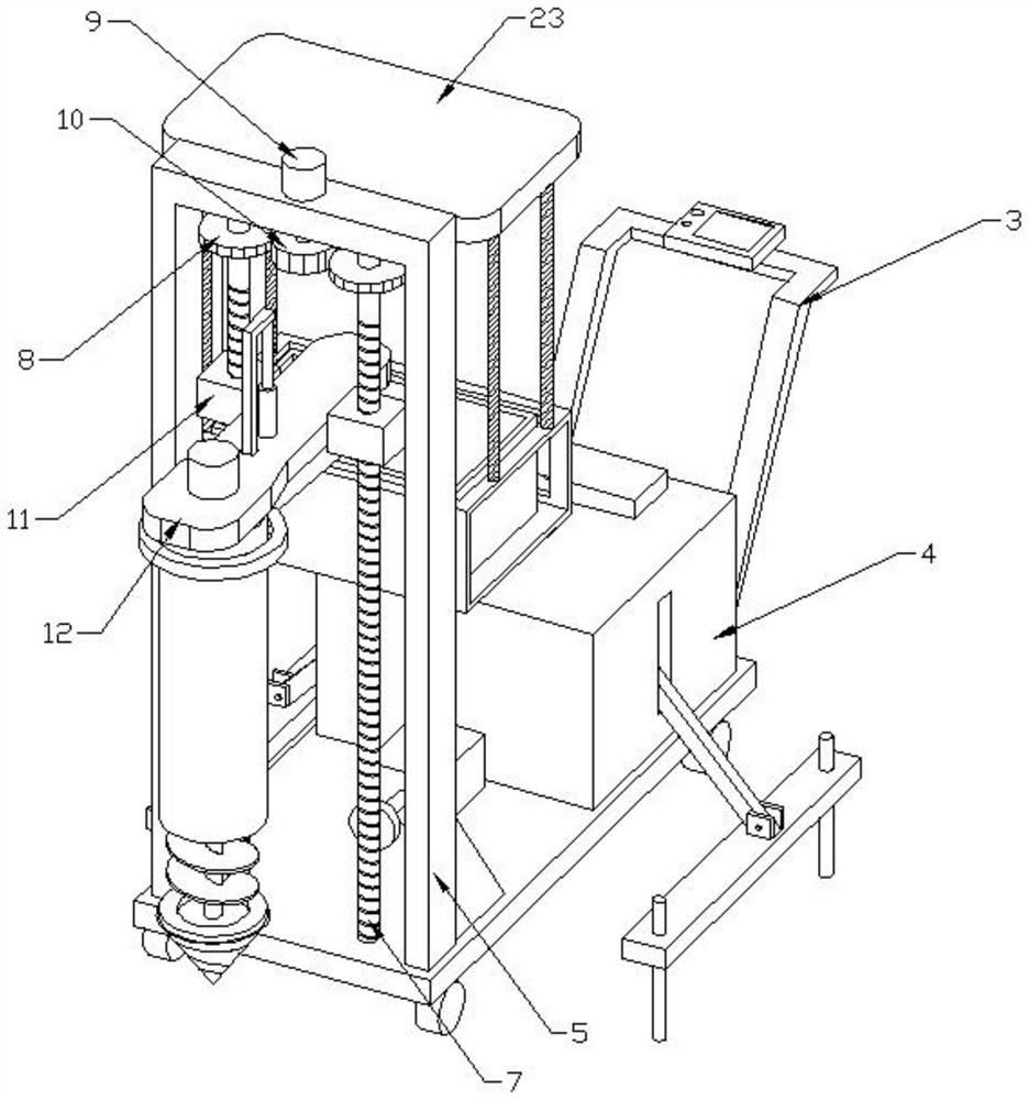
[0027] see Figure 1-7 As shown, this embodiment is a drilling and sampling device for geological exploration, including a base 1, the four corners of the bottom of the base 1 are equipped with moving wheels 2, the right side wall of the base 1 is connected with a push rod 3, and the upper end of the push rod 3 is connected with a control wheel. The panel, the top right side of the base 1 is connected with the outer shell 4, the top left side of the base 1 is connected with the guide frame 5, the guide frame 5 is arranged in a U-shaped structure, and the vertical end of the guide frame 5 is welded with a reinforcing rib on the top of the base 1 6. There are two screw rods 7 connected in rotation between the transverse end of the guide frame 5 and the base 1, the driven gear 8 is connected to the top of the outer wall of the screw rod 7, the drive motor 9 is connected to the top of the transverse end of the guide frame 5, and the drive motor 9 The power output end of the bottom...

Embodiment 2

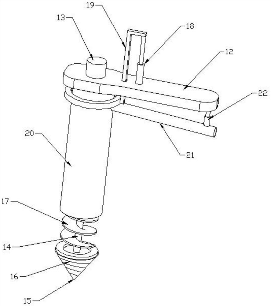
[0033] On the basis of Embodiment 1, the top left side of the drilling base 12 is connected with a drilling motor 13, the bottom power output end of the drilling motor 13 is connected with a drill rod 14, and the bottom of the drill rod 14 is connected with a conical head 15. The outer wall of the shaped head 15 is connected with a tapered drill edge 16, the top of the tapered head 15 is connected with a washer, the outer wall of the drill rod 14 is connected with an auger 17, the top of the drilling seat 12 is connected with an electric telescopic rod 18, and the electric telescopic rod 18 The movable end of the installation frame 19 is connected with a mounting frame 19, and the lower end of the mounting frame 19 is connected with a limit sleeve 20. The limit sleeve 20 is movably set outside the auger 17, and the right end of the limit sleeve 20 is connected with a discharge pipe 21. A free telescopic rod 22 is connected between the top right side of the material pipe 21 and ...


PUM


Abstract

The invention discloses a drilling sampling device for geological exploration; the device comprises a base, a push rod is connected to the right side wall of the base, a control panel is connected to the upper end of the push rod, an outer shell is connected to the right side of the top of the base, a guide frame is connected to the left side of the top of the base and is of a U-shaped structure, and a reinforcing rib is welded between the vertical end of the guide frame and the top of the base; two lead screws are rotationally connected between the transverse end of the guide frame and the base, driven gears are connected to the tops of the outer walls of the lead screws, a driving motor is connected to the top of the transverse end of the guide frame, a driving gear is connected to the power output end of the bottom of the driving motor, and the driving gear is in meshed connection with the driven gears. Nut seats are screwed on the outer walls of the lead screws; and a drilling seat is connected between the two nut seats; the drilling sampling device is reasonable in structural design, the stability of the device in use is improved, soil of different depths can be sampled conveniently, bottom layer soil can be conveyed upwards along the limiting sleeve, and an operator can take out a soil sample in the sample box conveniently.

Description

technical field [0001] The invention relates to the technical field of geological exploration equipment, in particular to a drilling sampling device for geological exploration. Background technique [0002] Geological prospecting is the investigation and research activity of conducting geological exploration and detection through various means and methods, determining the appropriate bearing layer, determining the foundation type and calculating the foundation parameters according to the foundation bearing capacity of the bearing layer. It is the discovery of mineral deposits with industrial significance in the general survey of mineral resources. In order to ascertain the quality and quantity of mineral products, as well as the technical conditions for mining and utilization, provide mineral reserves and geological data required for mine construction design, and analyze rocks and strata in a certain area. Conduct investigation and research work on geological conditions such...

Claims


Application Information

Patent Timeline
Patent Type & Authority Applications(China)
IPC IPC(8): G01N1/08
CPCG01N1/08
Inventor 刘晟辰
Owner 刘晟辰
Learn More