Underground water sampling device for hydrogeology

A sampling device and hydrogeological technology, applied in sampling devices, measuring devices, sampling and other directions, can solve the problems of limiting the scope of water sampling and unfavorable outdoor sampling work by convenient personnel.

Inactive Publication Date: 2021-11-19
张振杰
View PDF0 Cites 0 Cited by
  • Summary
  • Abstract
  • Description
  • Claims
  • Application Information

AI Technical Summary

Problems solved by technology

[0004] The water bodies in various states buried in the voids of the rocks below the surface are called groundwater, and when sampling equipment is used to sample the groundwater in the voids of rock and soil below the ground outdoors, due to the different sizes of the voids at the sampling points, the water intake of the sampling equipment Fixed in a columnar shape, it limits the scope of water sampling, which is not conducive to the outdoor sampling work of convenient personnel

Method used


Image

  • Underground water sampling device for hydrogeology
  • Underground water sampling device for hydrogeology
  • Underground water sampling device for hydrogeology

Examples


Embodiment 1

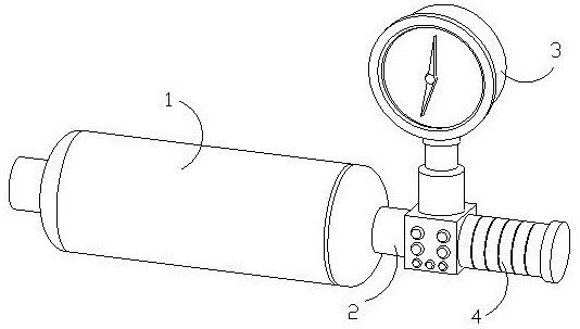
[0031] as attached figure 1 to attach Figure 5 Shown:

[0032] The present invention provides a groundwater sampling device for hydrogeology, the structure of which is provided with a sampling cylinder 1, a connecting column 2, a pressure gauge 3, and a handle 4, and the connecting column 2 is embedded and connected to one side of the sampling cylinder 1 and connected internally. , the pressure gauge 3 is arranged on one side of the connecting column 2, and the handle 4 is fixedly connected to one side of the lower end of the pressure gauge 3.

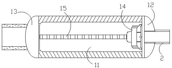
[0033] The sampling cylinder 1 is provided with a water collection chamber 11, a front cover 12, a sampling device 13, a pump 14, and a suction pipe 15. The front cover 12 is bolted to one side of the water collection chamber 11, and the sampling device 13 is connected to the water collection chamber 11. The water collecting chamber 11 is an integrated structure and is located at one side end thereof. The pump 14 is fixedly installe...

Embodiment 2

[0039] as attached Figure 6 to attach Figure 9 Shown:

[0040] Wherein, the diameter reducing device a3 is provided with a clamping block a31, a magnetic block a32, and a mouth control device a33, the clamping block a31 is fixedly connected with the magnetic block a32, and the mouth control device a33 is connected inside the clamping block a31. The clamping block a31 is embedded in the moving rail a1, the magnetic block a32 is slidingly engaged with the moving rail a1, the magnetic block a32 has a certain magnetic force, and the mouth control device a33 has a circular structure and can be expanded in a ring shape. Shrinking deformation, the mouth control device a33 changes with the displacement of the block a31, and performs annular expansion and contraction during the change to make the water intake diameter mouth change.

[0041] Wherein, the mouth control device a33 is provided with an outer limit plate c1, a ring block c2, a matching body c3, and a water flow path c4, ...


PUM


Abstract

The invention discloses an underground water sampling device for hydrogeology; the device is structurally provided with a sampling cylinder, a connecting column, a pressure gauge and a handle, the connecting column is fixedly connected to one side end of the sampling cylinder in an embedded mode and internally communicated with the sampling cylinder, the pressure gauge is arranged at one side end of the connecting column, and the handle is fixedly connected to one side of the lower end of the pressure gauge. A rolling ball rolls in a grooved rail; a magnetic ball is assisted in moving at the upper end and lower end under the push; a peripheral frame can be obliquely placed from the horizontal direction under the telescopic cooperation of supporting feet, the supporting feet at the two side ends do relative telescopic motion, the tail end of the peripheral frame is ejected, and then the front end and the rear end of a deformation block are extruded differently, so that the deformation block is subjected to toughness deformation better; a cylindrical cavity-shaped diameter opening of a water taking device tends to change in a conical cavity shape, so that the water taking device can extend into the ground surface gap due to the change of the diameter opening width, and the equipment can better adapt to different sampling points when personnel collect surface water outdoors.

Description

technical field [0001] The invention belongs to the field of water quality sampling equipment, and more specifically relates to a groundwater sampling device for hydrogeology. Background technique [0002] As an important energy resource of nature, water resources can be sampled and tested to allow personnel to know the status of the water body and understand the composition parameters and characteristics of the water body in a timely manner. The groundwater sampling device for hydrogeology is specially used for water quality sampling. It uses pumps and The mutual cooperation of the water suction pipes sucks the groundwater into the collection cylinder cavity, and completes the sampling operation of the groundwater. [0003] Based on above-mentioned inventor's discovery, there is following deficiency in existing groundwater sampling device for hydrogeology: [0004] The water bodies in various states buried in the voids of the rocks below the surface are called groundwater,...

Claims


Application Information

Patent Timeline
Patent Type & Authority Applications(China)
IPC IPC(8): G01N1/14
CPCG01N1/14G01N2001/1427
Inventor 张振杰冯嘉兴
Owner 张振杰
Why Eureka
Try Eureka