
Noise reduction nozzle adjusted by rotating structure

A technology of rotating structure and nozzle, applied in the direction of spraying device, spraying device, etc., can solve the problems of less consideration of nozzles, inconvenient adjustment of distance, and inability to adjust, so as to change the sudden change of airway cross-sectional area, improve the applicable surface and flexibility , the effect of increasing the circulation area

Active Publication Date: 2021-11-23
ZHEJIANG UNIV OF TECH
View PDF12 Cites 7 Cited by
  • Summary
  • Abstract
  • Description
  • Claims
  • Application Information

AI Technical Summary

Problems solved by technology

[0003]Nozzle is an important component to achieve droplet atomization and effective spraying of gas-liquid mixture, but the design process of existing nozzles often only considers atomization effect, spray distance, etc. Technical indicators, without considering the impact of nozzle noise on the environment, lack of optimized design for reducing nozzle noise, and its structure generally has the following problems:
[0005](2) The distance from the liquid pipe head to the nozzle opening is not easy to adjust, and it is not suitable for the conversion of different application scenarios
In different application conditions, there are differences in air pressure and liquid flow. In order to achieve the ideal atomization effect in application conditions, it is often necessary to adjust the distance between the liquid pipe head and the nozzle opening, but the structure of existing nozzles is rarely considered. The design scheme to facilitate the adjustment of the distance between the liquid pipe head and the nozzle opening cannot be adjusted flexibly according to actual needs

Method used


Image

  • Noise reduction nozzle adjusted by rotating structure
  • Noise reduction nozzle adjusted by rotating structure
  • Noise reduction nozzle adjusted by rotating structure

Examples


Embodiment Construction

[0023] specific implementation

[0024] The following will clearly and completely describe the technical solutions in the embodiments of the present invention with reference to the accompanying drawings in the embodiments of the present invention. Obviously, the described embodiments are only some, not all, embodiments of the present invention. Based on the embodiments of the present invention, all other embodiments obtained by persons of ordinary skill in the art without creative efforts fall within the protection scope of the present invention.

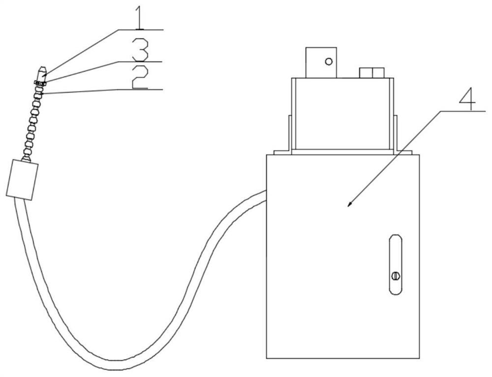
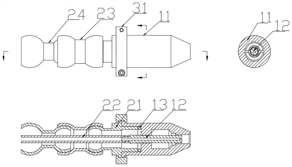
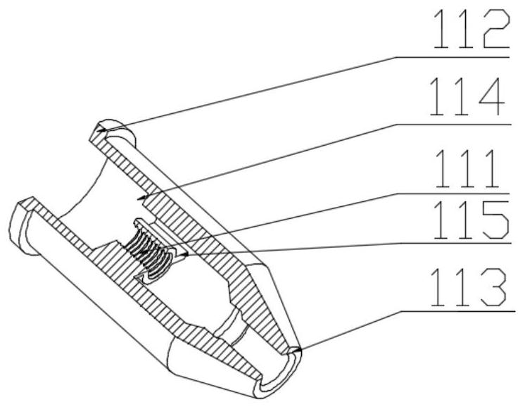
[0025] Such as Figure 1-7 As shown, a noise-reducing nozzle adjusted by a rotating structure according to the present invention mainly includes a nozzle 1 , a connecting component 2 and a fastening component 3 . Its feature is to adjust the distance between the liquid pipe head 124 and the nozzle opening 113 by rotating the nozzle head 11, so as to achieve the effect of controlling the noise and adjusting the atomization degree of...


PUM


Abstract

The invention provides a noise reduction nozzle adjusted by a rotating structure. The noise reduction nozzle mainly comprises a nozzle body, a connecting assembly and a fastening assembly. The nozzle body comprises a nozzle head and a liquid pipe. The nozzle head is of a hollow structure, a liquid pipe fixing hole is formed inside the nozzle head, threads are machined inside the liquid pipe fixing hole, and the liquid pipe fixing hole is connected with the outer wall of the nozzle head through a side wing plate. A nozzle head inner ring table is arranged at the end, far away from an outlet of the nozzle head, of the liquid pipe fixing hole and used for installation of a rubber gasket. A nozzle head outer convex ring table is arranged at the end, far away from an outlet of the nozzle body, of the nozzle head. Threads are arranged on the outer wall of the liquid pipe and combined with the threads located inside the liquid pipe fixing hole in a screwed mode. According to the noise reduction nozzle, the nozzle structure which is characterized in that the side wing plate is connected with the coaxial internal threads is designed, and therefore the circulation area of an air channel is enlarged, and the internal noise is reduced; and meanwhile, adjustment of the distance between a liquid pipe head and a nozzle opening can be adjusted by screwing of the external threads of the liquid pipe and the external threads on the nozzle head.

Description

technical field [0001] The invention belongs to the technical field of mechanical equipment, and in particular relates to a noise reduction nozzle adjusted by a rotating structure. Background technique [0002] The use of high-pressure gas to atomize liquid droplets is a commonly used method for making sprays. Its realization is as follows: the air flow and liquid are collected into a mutually nested pipe through the manifold, the liquid is transported by the central pipe, and the air flow passes through the inner and outer pipes. The gap between them flows, and the droplets are atomized and ejected at the nozzle. This method is commonly used in industrial production to realize the directional delivery of cooling liquid or lubricating liquid. [0003] The nozzle is an important component to realize the atomization of droplets and the effective injection of gas-liquid mixture. However, in the design process of existing nozzles, only technical indicators such as atomization e...

Claims


Application Information

Patent Timeline
IPC IPC(8): B05B1/00B05B15/65
CPCB05B1/002B05B15/65
Inventor 胡晓冬李元龙许雪峰张若冲王明环
Owner ZHEJIANG UNIV OF TECH
Learn More