Gasoline engine ignition mechanism comprising supersonic jet orifice pre-combustion chamber
An ignition mechanism and pre-combustion chamber technology, which is applied to combustion engines, machines/engines, internal combustion piston engines, etc., can solve the problems of difficult ignition of mixture gas and slow combustion speed of mixture gas, so as to reduce fuel consumption and improve combustion Performance, the effect of extending the lean burn limit
- Summary
- Abstract
- Description
- Claims
- Application Information
AI Technical Summary
Problems solved by technology
Method used
Image
Examples
Embodiment 1
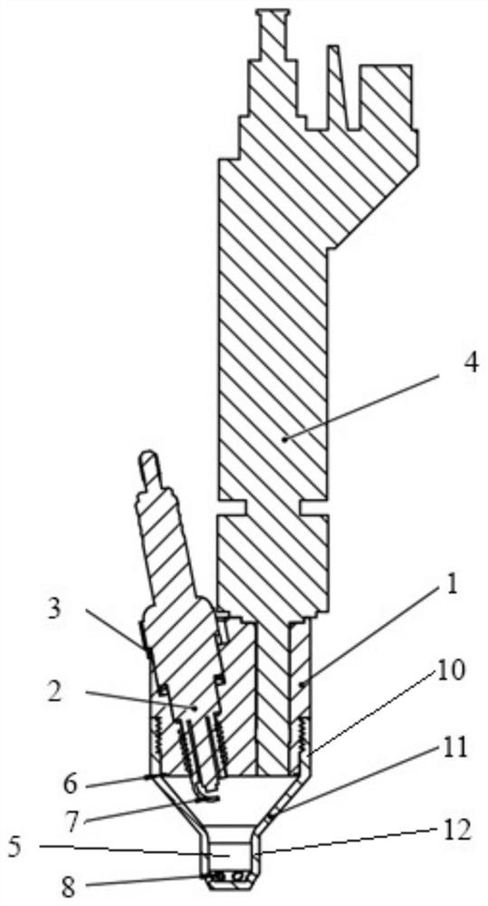
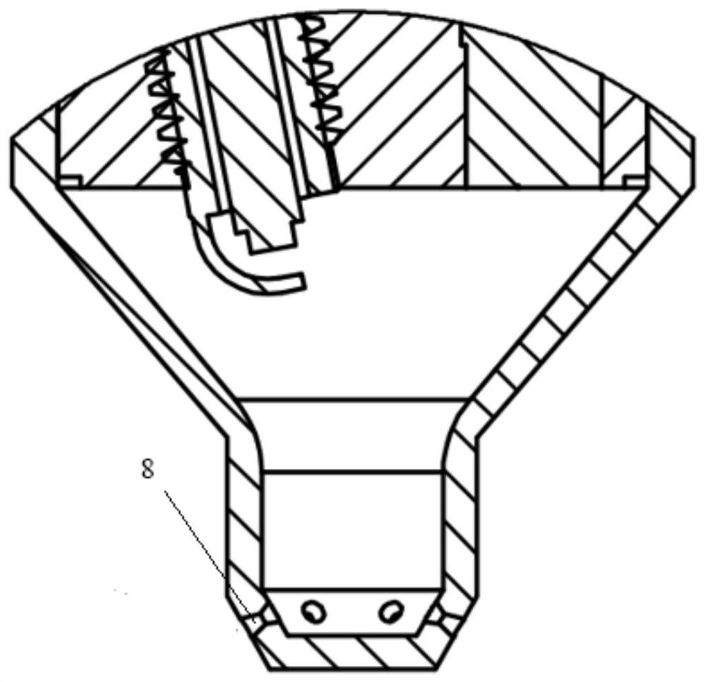
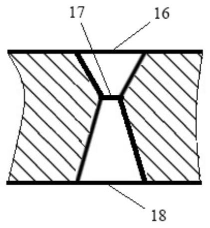
[0034] combine Figure 1-6 , to illustrate the specific implementation scheme of this embodiment.
[0035] The main combustion chamber of the engine used in conjunction with the present embodiment is "hemispherical".
[0036] An ignition mechanism for a gasoline engine comprising a supersonic jet orifice pre-combustion chamber, comprising: a cylindrical connecting piece 1, a fuel injector mounting hole penetrating through the upper end surface and the lower end surface of the connecting piece, and a spark plug penetrating through the upper end surface and the lower end surface of the connecting piece Mounting hole, pre-combustion chamber cavity 5 connected to the outer peripheral surface of the connector through threads, pre-chamber injector 4 working with the injector mounting hole, pre-chamber spark plug 2 working with the spark plug mounting hole, spark plug Gasket 3, sealing gasket 6;
[0037] The above-mentioned spark plug gasket realizes the sealing between the pre-cha...
Embodiment 2
[0048] Control attached Figure 7-9 , the main combustion chamber of the engine used in conjunction with the present embodiment is "canopy shape". The ignition mechanism is installed in the center of the "canopy" main combustion chamber cylinder head.
[0049] Among the above nozzle holes, 2 are supersonic overexpansion jet nozzle holes 8, and 4 are ordinary subsonic direct injection holes 9; Two subsonic ordinary direct injection holes are arranged on both sides of the "canopy" concave.
[0050] The rest of the structure is exactly the same as that of Embodiment 1, and the working process is also completely the same as that of Embodiment 1.
[0051] In view of the structural design features of the "canopy" main combustion chamber, a mixed configuration of supersonic jet nozzles and subsonic ordinary direct injection holes is adopted to achieve balanced combustion of the mixture gas in each part of the main combustion chamber as much as possible, which is conducive to improv...
Embodiment 3
[0053] Control attached Figure 10-12 , the main combustion chamber of the engine used in conjunction with the present embodiment is "canopy shape". The ignition mechanism is mounted offset in the position of the "canopy" main combustion chamber cylinder head;
[0054] Among the above nozzle holes, 3 are supersonic overexpansion jet nozzles 8, and 3 ordinary subsonic direct injection holes 9; the subsonic ordinary direct injection holes point to the narrower part of the jet space, and the overexpanded supersonic jet nozzle points to the jet distance farther away.
[0055] The rest of the structure is exactly the same as that of Embodiment 1, and the working process is also completely the same as that of Embodiment 1.
[0056] In view of the structural design features of the "canopy" main combustion chamber, a mixed configuration of supersonic jet nozzles and subsonic ordinary direct injection holes is adopted to achieve balanced combustion of the mixture gas in each part of ...
PUM
 Abstract
Description
Claims
Application Information
 - R&D
- Intellectual Property
- Life Sciences
- Materials
- Tech Scout
- Unparalleled Data Quality
- Higher Quality Content
- 60% Fewer Hallucinations
Browse by: Latest US Patents, China's latest patents, Technical Efficacy Thesaurus, Application Domain, Technology Topic, Popular Technical Reports.
© 2025 PatSnap. All rights reserved.Legal|Privacy policy|Modern Slavery Act Transparency Statement|Sitemap|About US| Contact US: help@patsnap.com


