
Pulverized coal adding device of thermal power generation equipment

Pending Publication Date: 2021-11-23
NORTH UNITED POWER CO LTD
View PDF12 Cites 2 Cited by
  • Summary
  • Abstract
  • Description
  • Claims
  • Application Information

AI Technical Summary

Problems solved by technology

[0003] Power plants are paying more and more attention to fuel utilization and energy saving and emission reduction. In order to improve power generation efficiency, some additives are often added to the combustion furnace to ensure combustion efficiency. However, the existing adding methods will make the additive distribution not uniform enough to fully contact with coal powder. As a result, the additives cannot fully react at the first time, and the utilization rate is relatively low

Method used


Image

  • Pulverized coal adding device of thermal power generation equipment
  • Pulverized coal adding device of thermal power generation equipment
  • Pulverized coal adding device of thermal power generation equipment

Examples


Embodiment 1

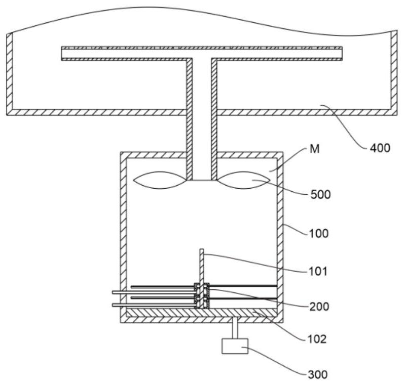
[0030] refer to figure 1 and figure 2 , is the first embodiment of the present invention, this embodiment provides a kind of pulverized coal addition device of thermal power generation equipment, the pulverized coal addition device of thermal power generation equipment comprises mixing chamber 100, addition unit 200, air compressor 300, furnace Body 400 and exhaust unit 500.

[0031] An accommodating space M is provided inside the mixing chamber 100 , and a column 101 is arranged in the accommodating space M, and the column 101 is coaxially arranged with the mixing chamber 100 .

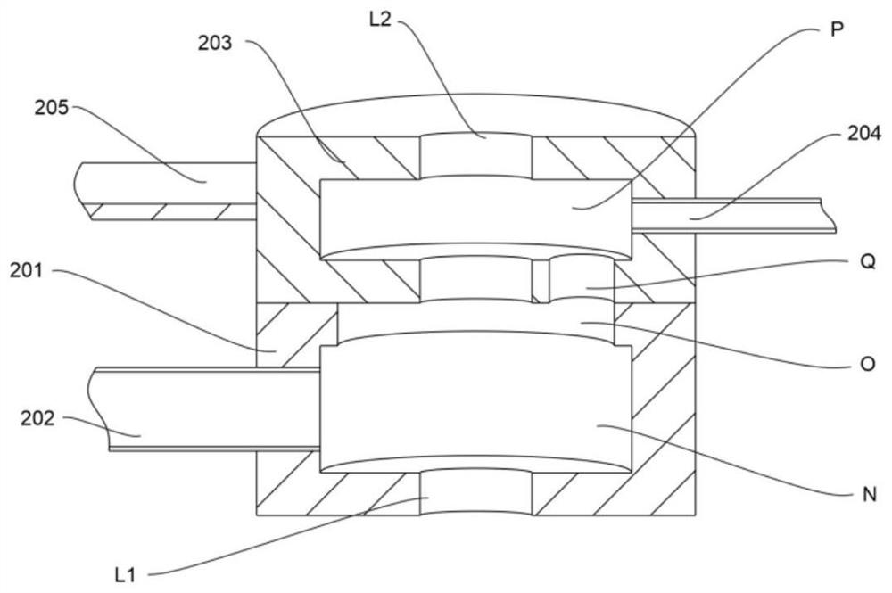
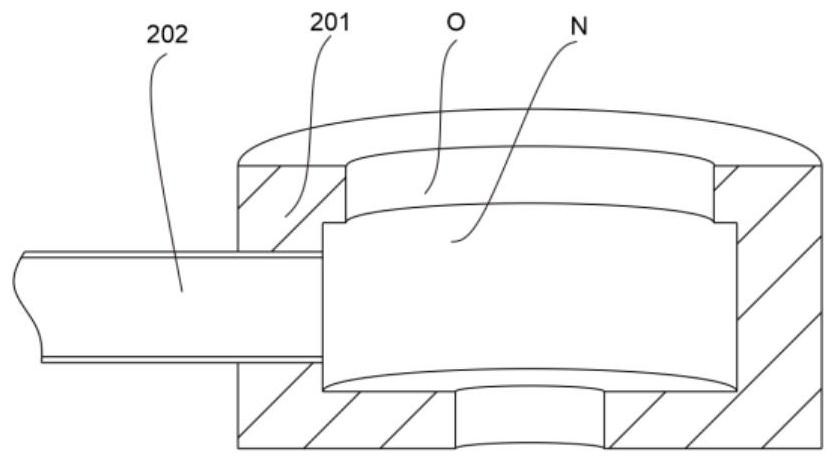
[0032] The adding unit 200 includes a mounting base 201, an air intake pipe 202, a rotating base 203 and an air outlet pipe 204, the mounting base 201 is installed on the column 101, the air intake pipe 202 communicates with the mounting base 201, and the rotating base 203 is rotationally connected with the mounting base 201, the outlet pipe 204 is connected with the rotating base 203, the mountin...

Embodiment 2

[0038] refer to Figure 1~6 , is the second embodiment of the present invention, which is different from the first embodiment.

[0039] Specifically, the exhaust unit 500 includes a connecting pipe 501, the connecting pipe 501 is arranged between the accommodating space M and the furnace body 400, one end is rotatably connected to the mixing chamber 100, and the other end is connected to the The furnace body 400 is rotatably connected.

[0040] Further, the exhaust unit 500 also includes a stirring fan 502, which is located in the accommodating space M and installed at one end of the connecting pipe 501; when the agitating fan 502 is working, the accommodating The wind in the space M rotates, and the rotating wind has the property of converging, that is, the gas is converging towards the middle position.

[0041] Preferably, the exhaust unit 500 also includes an exhaust pipe 503, the exhaust pipe 503 is installed at the other end of the connecting pipe 501, and is also provi...

Embodiment 3

[0044] refer to Figure 1-7 , is the third embodiment of the present invention, which is different from the first two embodiments:.

[0045] Specifically, the mixing chamber 100 also includes a diffuser plate 102, the diffuser plate 102 is installed at the bottom of the mixing chamber 100, and is also provided with a plurality of through holes 102a, a plurality of the through holes 102a It communicates with the output end of the air compressor 300; the air flow of the air compressor 300 is divided into multiple streams, which can disturb the air flow at the bottom of the mixing chamber 100, thereby allowing different additives to be quickly mixed.

[0046] Further, at least one through hole 102a is provided on any radius of the diffuser plate 102; this can ensure that no matter where the inclined plate 205 is in the mixing chamber 100, the air blown out from the air compressor 300 All the gas can act on the inclined plate 205, thereby ensuring that the rotating base 203 can r...


PUM


Abstract

The invention discloses pulverized coal adding device of thermal power generation equipment. The pulverized coal adding device of the thermal power generation equipment comprises a material mixing chamber, an adding unit, an air compressor, a furnace body and an exhaust unit, wherein the material mixing chamber is provided with a containing space and comprises a stand column coaxial with the material mixing chamber; the stand column is arranged in the containing space; the adding unit comprises a mounting seat, an air inlet pipe, a rotating seat and an air outlet pipe; the mounting seat is provided with an air inlet cavity and an annular groove communicated with the air inlet cavity; the rotating seat is provided with a transition cavity and an opening; the transition cavity is communicated with the annular groove through the opening; the output end of the air compressor is communicated with the containing space; the furnace body is communicated with the material mixing chamber; and the furnace body is communicated with the material mixing chamber through the exhaust unit. According to the device provided by the invention, additives can rotate along with the rotating seat and the air outlet pipe before entering the material mixing chamber, so that the effect of quickly and uniformly mixing different additives is achieved, the additives and pulverized coal can be mixed more uniformly when the additives enter the furnace body, and the utilization rate of the additives is increased.

Description

technical field [0001] The invention relates to the technical field of thermal power generation, in particular to a pulverized coal adding device for thermal power generation equipment. Background technique [0002] Thermal power generation is a power generation method that uses the heat energy generated by combustibles during combustion and converts it into electrical energy through a power generation device. In order to improve comprehensive economic benefits, thermal power generation should be carried out as close as possible to the fuel base. [0003] Power plants are paying more and more attention to fuel utilization and energy saving and emission reduction. In order to improve power generation efficiency, some additives are often added to the combustion furnace to ensure combustion efficiency. However, the existing adding methods will make the additive distribution not uniform enough to fully contact with coal powder. As a result, the additive cannot fully react at th...

Claims


Application Information

Patent Timeline
IPC IPC(8): F23K1/00F23K3/02B01F15/02B01F7/22B01F27/91
CPCF23K1/00F23K3/02
Inventor 许俊锋王䶮飞
Owner NORTH UNITED POWER CO LTD
Features
  • Generate Ideas
  • Intellectual Property
  • Life Sciences
  • Materials
  • Tech Scout
  • Unparalleled Data Quality
  • Higher Quality Content
  • 60% Fewer Hallucinations
Learn More