Supercharge Your Innovation With Domain-Expert AI Agents!

Optical element defect detection system and detection method

A technology of defect detection and optical components, applied in the direction of material analysis, measuring devices, scientific instruments, etc. through optical means, can solve problems such as dependence, defect shape misjudgment, defect location error, etc., to solve the problem of defect shape misjudgment and defect positioning errors, improve the accuracy of defect detection, and reduce the effect of defect positioning errors

Pending Publication Date: 2021-11-23
LASER FUSION RES CENT CHINA ACAD OF ENG PHYSICS
View PDF0 Cites 0 Cited by
  • Summary
  • Abstract
  • Description
  • Claims
  • Application Information

AI Technical Summary

Problems solved by technology

The manual inspection process requires the inspectors to judge the defect morphology characteristics with the help of inspection tools and manually mark the defects. This process relies heavily on the experience of the inspectors.
Although manual inspection can detect defects in time and greatly improve the qualified rate of finished products of optical components, however, in the process of manual inspection, it is inevitable that there will be some misjudgments of defect appearance and defect positioning errors caused by human factors.

Method used


Image

  • Optical element defect detection system and detection method
  • Optical element defect detection system and detection method
  • Optical element defect detection system and detection method

Examples


Embodiment Construction

[0049] The following will clearly and completely describe the technical solutions in the embodiments of the present invention with reference to the accompanying drawings in the embodiments of the present invention. Obviously, the described embodiments are only some, not all, embodiments of the present invention. Based on the embodiments of the present invention, all other embodiments obtained by persons of ordinary skill in the art without making creative efforts belong to the protection scope of the present invention.

[0050] The first aspect of the embodiment of the present invention discloses an optical element defect detection system.

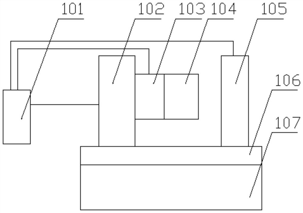
[0051] See attached figure 1 The schematic diagram of an optical component defect detection system is shown, including the following modules:

[0052] The positioning and clamping module 105 is used for positioning and clamping the test sample and automatically adjusting the posture of the test sample;

[0053] The defect detection module ...


PUM


Abstract

The invention discloses an optical element defect detection system and detection method, the system comprises a lathe bed supporting module, a vibration isolation module, a positioning clamping module, a defect detection module, a defect analysis module, a scanning motion module and an electrical control module, and each module completes the corresponding function. The method comprises the following specific working steps: starting equipment and software, carrying out system initialization setting, setting system parameters, placing a tested sample, setting measurement parameters, scanning and testing the sample, collecting detection data, analyzing defect types, evaluating defect characteristics and closing a result output system. According to the invention, the problems of defect morphology misjudgment and defect positioning errors possibly caused by some personnel reasons in manual inspection are solved, the occurrence rate of defect positioning errors is reduced, and the defect detection accuracy of the large-aperture optical component is further improved.

Description

technical field [0001] The invention relates to the field of ultra-precision processing and detection of optical components, in particular to micron / submicron defect testing during and after polishing of large-diameter optical components. Background technique [0002] The rapid development of modern large-scale optical engineering puts forward strict requirements on the processing quality of optical components. Especially in the manufacturing process of large-diameter optical components, it is necessary to use the inspection process to detect defects on the polished surface of optical components to improve the pass rate of optical component processing, which requires large-diameter, high surface accuracy, ultra-smooth, and low-defect requirements. According to the different inspection subjects, the inspection process can be divided into equipment inspection process and manual inspection process. The equipment inspection process is mainly used for small-caliber sample proces...

Claims


Application Information

Patent Timeline
IPC IPC(8): G01N21/958
CPCG01N21/8851G01N21/958G01N2021/8854G01N2021/8887
Inventor 袁志刚郑楠李洁陈贤华韦前才周炼赵世杰邓文辉钟波侯晶
Owner LASER FUSION RES CENT CHINA ACAD OF ENG PHYSICS
Features
  • R&D
  • Intellectual Property
  • Life Sciences
  • Materials
  • Tech Scout
  • Unparalleled Data Quality
  • Higher Quality Content
  • 60% Fewer Hallucinations
Learn More