Regenerative braking energy storage coordination control method and system

A technology of coordinated control and regenerative braking, applied in system integration technology, information technology support system, electric vehicles, etc., can solve the problems of uncoordination, large capacity redundancy, high equipment configuration cost, etc., achieve stable DC network voltage, reduce The activation probability and the effect of improving the response speed

Pending Publication Date: 2021-11-23
南京国电南自新能源科技有限公司
View PDF0 Cites 0 Cited by
  • Summary
  • Abstract
  • Description
  • Claims
  • Application Information

AI Technical Summary

Problems solved by technology

[0003] In the actual operation of urban rail transit lines, since the braking energy is affected by parameters such as vehicle running speed, passenger capacity and row density, the braking energy that different traction stations can absorb is not the same, but most of the actual engineering design configurations Capacitive energy storage devices with the same capacity, so the power output of the devices of different traction stations is unbalanced and uncoordinated, that is, some devices have insufficient capacity to absorb braking energy, and some devices still have remaining capacity
On the other hand, since the energy storage device used in the braking energy capacitive energy storage device is a supercapacitor (electric double layer capacitor), if only the magnitude of the braking energy is obtained through simulation in the design stage and the equipment capacity is configured accordingly, the redundant capacity larger
In addition, if the up and down trains enter the station at the same time or the equipment of a certain station is out of operation due to failure or maintenance, the cost of equipment configuration will be higher

Method used


Image

  • Regenerative braking energy storage coordination control method and system
  • Regenerative braking energy storage coordination control method and system

Examples


Embodiment Construction

[0030] In order to further describe the technical features and effects of the present invention, the present invention will be further described below in conjunction with the accompanying drawings and specific embodiments.

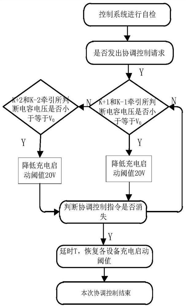
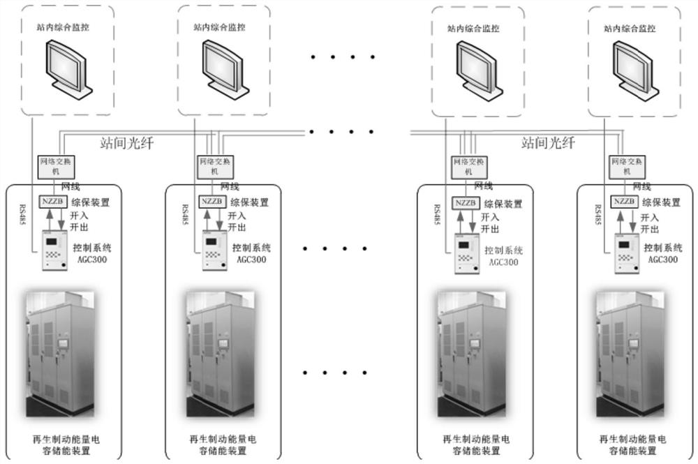
[0031] In order to implement the regenerative braking energy storage coordination control method described in the present invention, each traction station is provided with a regenerative braking energy capacitive energy storage device, a comprehensive protection device and a switch, and the traction stations are connected to each other through the switch to form a ring Type network or chain network, the connection between traction stations adopts the Goose communication protocol, only the transmission of switching values, and can realize ms-level communication. The control of the capacitive energy storage devices for regenerative braking energy among the traction stations is a peer-to-peer control relationship, and there is no master-slave distinction.

[...


PUM


Abstract

The invention discloses a regenerative braking energy storage coordination control method. The method comprises the steps: acquiring a coordination control request of a regenerative braking energy capacitor energy storage device in a traction station to be subjected to coordination control; judging the capacitance state of a regenerative braking energy capacitance energy storage device in a traction station adjacent to a traction station to be coordinated and controlled, and carrying out power support on the traction station to be coordinated and controlled according to the capacitance energy storage state of the regenerative braking energy capacitance energy storage device. When a regenerative braking energy capacitor energy storage device of a certain station is out of operation or reaches the maximum absorption power due to faults and maintenance, the control system of the capacitance energy storage device of the station transmits the quit or full power information of the device to the capacitance energy storage device of the adjacent station through the inter-station connection optical fiber, power support is carried out, the direct current network voltage is stabilized to the maximum extent, and the starting probability of a vehicle-mounted resistor and a brake shoe is reduced.

Description

technical field [0001] The invention belongs to the technical field of regenerative braking, and in particular relates to a regenerative braking energy storage coordination control method and system. Background technique [0002] During the operation of urban rail transit, due to its heavy weight and fast driving speed, frequent braking will generate a large amount of braking energy. If this part of braking energy is not absorbed and utilized, it will cause a rapid increase in the DC catenary voltage , threatening the safety of rail transit operation. At present, urban rail transit at home and abroad mostly consumes braking energy by installing resistance absorbing devices. This scheme converts braking energy into heat energy and consumes it, and the energy has not been effectively utilized. The braking energy capacitor energy storage device can increase or decrease the DC voltage to a controllable range through the converter and store it in the super capacitor, so as to ab...

Claims


Application Information

Patent Timeline
IPC IPC(8): H02J3/32H02J7/34H02J13/00
CPCH02J3/32H02J7/345H02J13/00006Y02E40/70Y02E60/00Y02B90/20Y04S10/14Y04S10/123Y04S40/12
Inventor 桑佳楠刘春松王结飞郭伟
Owner 南京国电南自新能源科技有限公司
Why Eureka
Try Eureka