
Solid-state transmitter monitoring control protection circuit and control method thereof

Active Publication Date: 2021-11-23
HAIHUA ELECTRONICS ENTERPRISECHINA CORP
View PDF8 Cites 0 Cited by
  • Summary
  • Abstract
  • Description
  • Claims
  • Application Information

AI Technical Summary

Problems solved by technology

The traditional emission protection pulse drive circuit usually uses AM26C32 for level conversion, and then uses multiple AM26C31 to drive and convert into multiple differential signals. It needs to use two chips, AM26C32 and AM26C31, and the peripheral circuit is relatively complicated.
[0004] The traditional pulse detection circuit uses AD sampling and is detected by a single-chip microcomputer. Since the single-chip microcomputer also needs to undertake other real-time tasks, it may cause a large delay in pulse detection, which limits the expansion ability of the control protection unit. At present, there is a lack of real-time and versatility. few technical solutions

Method used


Image

  • Solid-state transmitter monitoring control protection circuit and control method thereof
  • Solid-state transmitter monitoring control protection circuit and control method thereof
  • Solid-state transmitter monitoring control protection circuit and control method thereof

Examples


Embodiment

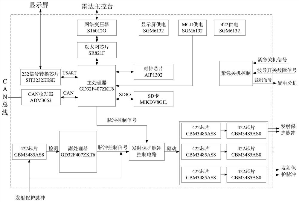
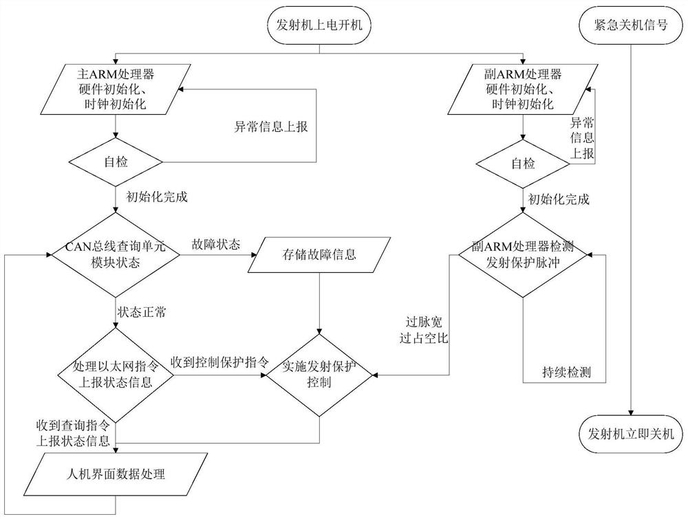
[0051] Such as figure 1 As shown, this embodiment provides a solid-state transmitter monitoring control protection circuit, which supports functions such as extended CAN communication, Ethernet communication, and serial port communication, including: a main ARM processor, a secondary ARM processor, a transmission pulse drive circuit, and a transmission pulse Detection circuit and emission pulse control circuit;

[0052] In this embodiment, the main ARM processor adopts a GD32F407ZKT6 chip, which is packaged in LQFP144, and is used as the main control chip of the transmitter monitoring control protection unit;

[0053] The sub-ARM processor adopts GD32F407RKT6 chip, which is packaged in LQFP64, and is used as the detection chip of the pulse detection circuit;

[0054] It is also equipped with a power supply circuit and an emergency shutdown control circuit. The power supply circuit includes a display power supply circuit, an MCU power supply circuit, and a 422 power supply cir...


PUM


Abstract

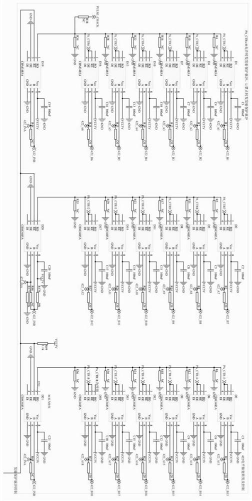
The invention discloses a solid-state transmitter monitoring control protection circuit and a control method thereof. The circuit comprises a main ARM processor, an auxiliary ARM processor, a transmission pulse drive circuit, a transmission pulse detection circuit and a transmission pulse control circuit. The main ARM processor responds to a control request of an upper computer or a power amplifier link to a transmission protection pulse, the transmission pulse drive circuit is provided with two stages of RS-485 chips, one path of transmission protection pulse is driven into two stages of multi-path transmission protection pulses, and the transmission pulse control circuit outputs a transmission protection pulse control signal; an RS-485 chip of the transmission pulse detection circuit converts a transmission protection pulse into a logic level and outputs the logic level from an RO end, and an auxiliary ARM processor detects the width and the duty ratio of the transmission pulse. According to the method, the main control logic and the pulse detection task are decoupled, the influence of frequent interruption of pulse detection on the main control logic can be avoided, and meanwhile, the real-time requirement and the driving capability requirement of a power amplifier link on protection pulse emission can be met.

Description

technical field [0001] The invention relates to the technical field of transmitter control, in particular to a solid-state transmitter monitoring control protection circuit and a control method thereof. Background technique [0002] The transmitter monitoring, control and protection unit is the unit of transmitter status monitoring and transmission protection pulse control, which mainly completes the detection and control of transmission protection pulses, provides transmission protection signals for the power amplifier link, and is responsible for responding to the control instructions of the host computer and collecting the Module status information, real-time reporting of transmitter status information to the host computer, and control and protection according to the status of the transmitter or unit module. [0003] The emission protection pulse is a necessary signal of the power amplifier link of the transmitter, and usually adopts the form of a differential signal with...

Claims


Application Information

Patent Timeline
Patent Type & Authority Applications(China)
IPC IPC(8): H04B1/04G01S7/282
CPCH04B1/04G01S7/282Y02E60/00
Inventor 宋朋郑德文李江武江蓉
Owner HAIHUA ELECTRONICS ENTERPRISECHINA CORP
Learn More