
Continuous liquid supply printing system and method for liquid metal 3D printing

A 3D printing and printing system technology, applied in the field of 3D printing, can solve the problems of 3D printing being blocked, affected, and the purity of liquid metal is not high

Active Publication Date: 2021-11-26
昆山晶微新材料研究院有限公司
View PDF4 Cites 0 Cited by
  • Summary
  • Abstract
  • Description
  • Claims
  • Application Information

AI Technical Summary

Problems solved by technology

The quality of 3D printing products is affected by the quality of the melt. If the melt is directly 3D printed without treatment, it will cause printing failure or serious product defects.
In addition, the ambient atmosphere of the melt will also have a significant impact on the smooth progress of 3D printing and the final 3D printed product.
[0004] The current liquid supply method is generally to directly melt the metal to form liquid metal, and then use the liquid metal for printing. This liquid supply method has the following problems: First, it cannot realize the continuous supply and automatic control of liquid metal, and cannot meet the needs of large-scale 3D printing. The demand for printed products; the second is that the purity of the prepared liquid metal is not high, which leads to the obstruction of the 3D printing process or defects such as pores, slag inclusions, and micro-cracks in the 3D printed products

Method used


Image

  • Continuous liquid supply printing system and method for liquid metal 3D printing

Examples


Embodiment 1

[0058] This embodiment provides a continuous liquid supply printing based on the continuous liquid supply printing system 100, which includes the following steps:

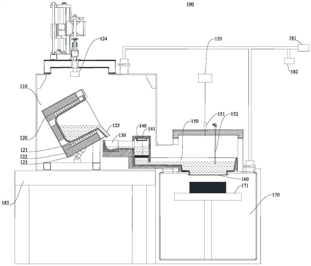
[0059] S1: The upper chamber 110 is evacuated by the vacuum pump 181, and the aluminum alloy is configured according to the composition ratio of 7150 aluminum alloy, that is, Si 0.12%, Fe 0.15%, Cu 1.9-2.5%, Mn 0.1%, Mg 2.0-2.7%, Cr 0.04%, Zn 5.9-6.9%, Zr 0.08-0.15, Ti 0.15, other impurities total 0.15%, put the massive or powdery material into the pouring crucible 120, turn on the switch of the heating coil 121, and heat the metal to 750 °C melts the metal.

[0060] S2: Start degassing treatment after the aluminum alloy is completely melted, turn on the rotary blower 124, and pass in argon gas for 30 minutes for degassing.

[0061] S3: Start the hydraulic control system 153 to tilt the pouring crucible 120, the molten metal flows from the pouring spout 125 into the melt receiving pool 130, and sequentially passes...

Embodiment 2

[0065] This embodiment provides a continuous liquid supply printing based on the continuous liquid supply printing system 100. Except that the step S4 of the liquid supply method is different from that in Embodiment 1, S1, S2, and S3 of the liquid supply system and the liquid supply method are the same as those in the embodiment. 1.

[0066] In this embodiment, the vacuum degree of the lower chamber 170 is 25kpa, the upper chamber 110 is argon, and the pressure difference is controlled at 35kpa.

Embodiment 3

[0068] This embodiment provides a continuous liquid supply printing based on the continuous liquid supply printing system 100. Except that the step S4 of the liquid supply method is different from that in Embodiment 1, S1, S2, and S3 of the liquid supply system and the liquid supply method are the same as those in the embodiment. 1.

[0069] In this embodiment, the lower chamber 170 is fed with argon at a pressure of 10 kpa, the upper chamber 110 is fed with argon at a pressure of 35 kpa, and the pressure difference is controlled at 10 kpa.


PUM


Abstract

The embodiment of the invention provides a continuous liquid supply printing system and method for liquid metal 3D printing, and relates to the technical field of 3D printing. The continuous liquid supply printing system comprises an inert gas supply station, a vacuum pump, an upper chamber and a lower chamber, wherein the upper chamber and the lower chamber are arranged up and down, and the inert gas supply station and the vacuum pump are respectively communicated with the upper chamber and the lower chamber in sequence; a pouring crucible, a melt purification pool and a melt storage pool are sequentially arranged in the upper chamber, the pouring crucible is configured to be capable of tilting towards the melt purification pool, a pouring nozzle is located above the melt purification pool, the melt purification pool is located on the melt storage pool, and the melt purification pool and the melt storage pool are separated through a ceramic filter plate; a nozzle is installed at the bottom of the melt storage pool, and the spraying direction faces the interior of the lower chamber; and a three-dimensional motion platform is arranged in the lower chamber. According to the continuous liquid supply printing system and method, high-purity liquid metal can be continuously provided, and the environment atmosphere where the liquid metal is located is guaranteed, so that manufacturing of 3D printing products with the large-size and high-performance requirements is achieved.

Description

technical field [0001] The present application relates to the technical field of 3D printing, in particular, to a continuous liquid supply printing system and method for liquid metal 3D printing. Background technique [0002] The materials involved in additive manufacturing technology cover metal materials, resins, paraffin, ceramics, etc., and have important application prospects in aerospace, marine, national defense and other fields. Metal additive manufacturing technology is a metal processing technology that slices the complex three-dimensional model of the part to be formed into a 2D section layer by layer, and then accumulates materials layer by layer along the height direction, and finally forms the metal part. Metal additive manufacturing technology has changed the traditional large-volume solidification casting mode, and the final product is prepared through continuous melting and superposition of micro-element areas, avoiding a series of shortcomings of convention...

Claims


Application Information

Patent Timeline
IPC IPC(8): B22F3/115C22C1/02C22C1/06C22C21/10B33Y10/00B33Y40/10B33Y30/00B33Y70/00
CPCB22F3/115B22F3/003C22C1/026C22C1/06C22C21/10B33Y10/00B33Y40/00B33Y30/00B33Y70/00Y02P10/25
Inventor 张佼姜海涛万祥辉东青
Owner 昆山晶微新材料研究院有限公司
Learn More