Testing system of side-by-side arrangement of high-speed pump and low-speed pump

A test system, high and low speed technology, applied in the direction of pump test, liquid variable displacement machinery, machine/engine, etc., can solve the problems of not meeting the test conditions, difficult maintenance, not thorough degassing, etc., to eliminate the interference of dissolved air bubbles , Improve the effect of precision, high reliability and safety

Active Publication Date: 2015-05-27
BEIHANG UNIV
View PDF10 Cites 0 Cited by
  • Summary
  • Abstract
  • Description
  • Claims
  • Application Information

AI Technical Summary

Problems solved by technology

At present, the speed of the turbopump used on the rocket has reached tens of thousands of revolutions per minute, while the speed of the test system of the pump on the ground is generally below 5000 revolutions per minute. The pump can only be simulated at a low speed by similar criteria, and because Some limitations, the ground test system cannot meet the requirements of different working conditions for test conditions, such as the degassing is not thorough enough, the heating system is inside the water tank, it is not easy to maintain, etc.

Method used


Image

  • Testing system of side-by-side arrangement of high-speed pump and low-speed pump

Examples


Embodiment Construction

[0035] The present invention will be further described in detail with reference to the accompanying drawings and embodiments.

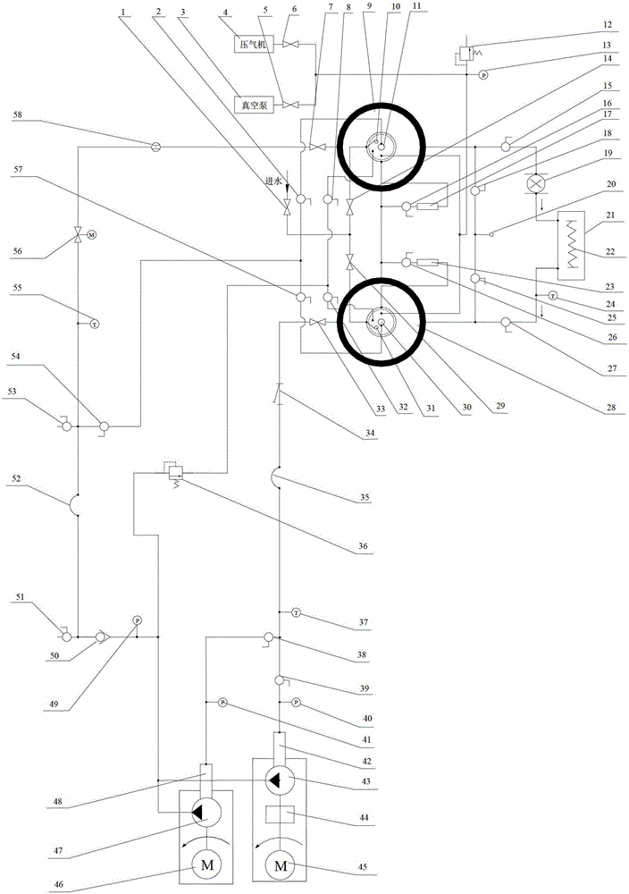
[0036] A kind of high and low speed pump test system arranged side by side of the present invention, such as figure 1 As shown, a closed circulation system is adopted, including the first shut-off valve 1, the fourteenth ball valve 2, the vacuum pump 3, the compressor 4, the fourth shut-off valve 5, the fifth shut-off valve 6, the seventh shut-off valve 7, and the ninth ball valve 8. Return water tank 9, first float valve 10, first nozzle 11, first safety valve 12, first pressure sensor 13, second stop valve 14, third ball valve 15, first ball valve 16, first liquid level Meter 17, fourth ball valve 18, water pump 19, water outlet 20, temperature control water tank 21, heating wire 22, second liquid level gauge 23, first temperature sensor 24, fifth ball valve 25, second ball valve 26, sixth ball valve 27. Outlet water tank 28, third stop valve 29, s...


PUM


Abstract

The invention discloses a testing system of side-by-side arrangement of a high-speed pump and a low-speed pump. According to the testing system of the side-by-side arrangement of the high-speed pump and the low-speed pump, the high-speed pump and the low-speed pump are arranged side by side and share one pipeline system, space of a laboratory is saved, and fast switch between the high-speed pump system and the low-speed pump system is achieved by opening and closing of a valve. The testing system of the side-by-side arrangement of the high-speed pump and the low-speed pump is composed of a system pipeline, a discharged water tank, a returned water tank, a vacuum pump, a compressor, the valve, a flow meter, a transparent shell, a filter, a high-low speed pump and a circulation water temperature control system. The testing system is a closed circulation system. Pre-pumping inlet pressure of the system is controlled by the vacuum pump and the compressor. An electric sleeve regulation valve controls flow of the system. Due to the fact that the discharged water tank and the returned water tank are independent, mutual interference of an inlet and an outlet is avoided. The circulation water temperature control system is capable of controlling temperature of water in the system. An over-pressure protection return circuit and a degassing return circuit are arranged at the post-pumping end, wherein the degassing return circuit separates gas from water in a return circuit through spray heads on the top of the water tanks, the gas is then pumped out by the vacuum pump, and therefore a good testing environment is guaranteed.

Description

technical field [0001] The invention relates to a test system for high and low speed pumps arranged side by side, in particular to a ground test system for rocket engine pumps. Background technique [0002] The turbo pump is a key component of the rocket engine. It is a linkage device that drives the pump by the turbine to pressurize the liquid propellant components. Aerospace has developed rapidly in the past ten years, and the requirements for pumps are getting higher and higher. Pumps are constantly developing towards miniaturization and high speed. Most pumps add an inducer before the centrifugal pump to improve the cavitation performance of the pump. At present, the speed of the turbopump used on the rocket has reached tens of thousands of revolutions per minute, while the speed of the test system of the pump on the ground is generally below 5000 revolutions per minute. The pump can only be simulated at a low speed by similar criteria, and because Some restrictions, th...

Claims


Application Information

Patent Timeline
Patent Type & Authority Patents(China)
IPC IPC(8): F04B51/00
Inventor 李家文蔡国飙李欣
Owner BEIHANG UNIV
Why Eureka
Try Eureka