

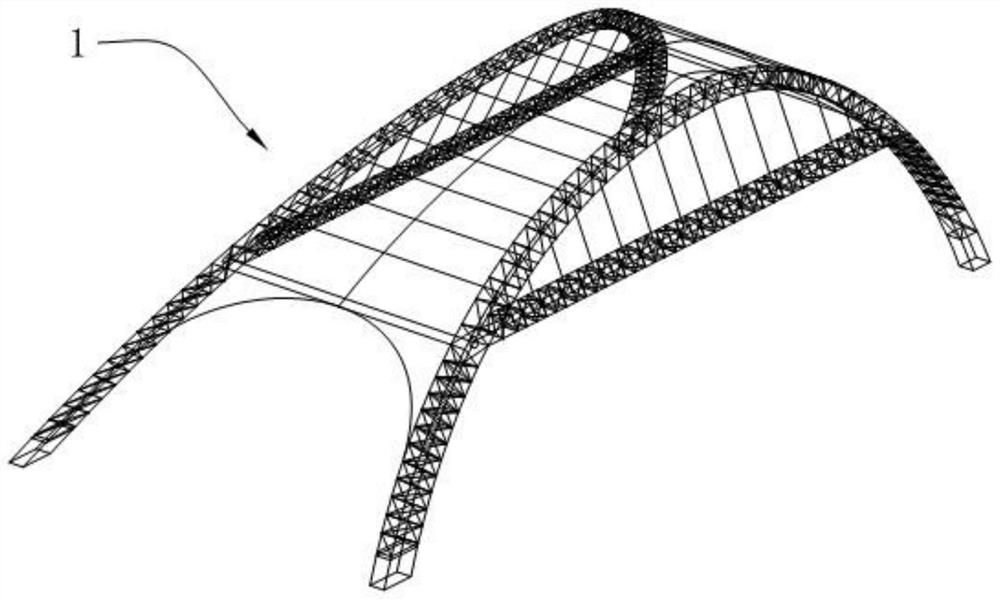
I-shaped bidirectional row pile foundation with prestressed pull rods and anti-push retaining walls
A technology of prestressed tie rods and I-shaped piles, which is applied in the direction of foundation structure engineering, arch bridges, buildings, etc., can solve the problems of being unable to bear horizontal loads, and cannot use inclined anti-push piles, so as to reduce the amount of concrete, self-weight and concrete The effect of reducing the amount and reducing the pile length
- Summary
- Abstract
- Description
- Claims
- Application Information
AI Technical Summary
Problems solved by technology
Method used
Image

Examples
Embodiment 1
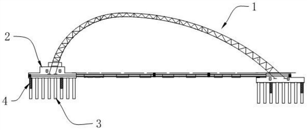
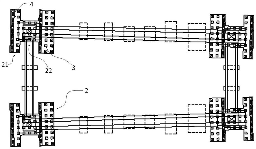
[0043] The plane size of the I-shaped pile cap 2 is 23200mm in length, 23200mm in width, 8200m in width at the top flange 21, 5200mm in width at the bottom flange 21, 11200mm in belly width, and 2500mm in thickness. 24 artificial hole-digging piles 3 are arranged, 16 artificial hole-digging piles 3 are arranged on the lower flange 21 part, 16 artificial hole-digging piles 3 are arranged on the web 22 part, the total number is 56, and the pile length of the artificial hole-digging piles 3 is 15m.
Embodiment 2
[0045] The plane size of the I-shaped pile cap 2 is 23200mm in length, 23200mm in width, 8200m in width at the top flange 21, 5200mm in width at the bottom flange 21, 11200mm in belly width, and 2500mm in thickness. 24 artificial hole-digging piles 3 are arranged, 16 artificial hole-digging piles 3 are arranged on the lower flange 21 part, 16 artificial hole-digging piles 3 are arranged on the web 22 part, the total number is 56, and the pile length of the artificial hole-digging piles 3 is 10m.
Embodiment 3
[0047]The plane size of the I-shaped pile cap 2 is 23200mm in length, 23200mm in width, 8200m in width at the top flange 21, 5200mm in width at the bottom flange 21, 11200mm in belly width, and 2500mm in thickness. 24 artificial hole-digging piles 3 are arranged, 16 artificial hole-digging piles 3 are arranged on the lower flange 21 part, 16 artificial hole-digging piles 3 are arranged on the web 22 part, the total number is 56, and the pile length of the artificial hole-digging piles 3 is 10m, at the upper and lower flanges 21 of the I-shaped pile cap 2, perpendicular to the projection line of the main arch 1 on the horizontal plane, two underground diaphragm walls 4 are respectively arranged to improve the ability of the foundation to resist the two-way horizontal thrust of the arch foot. The diaphragm wall 4 is arranged along the full width of the flange 21 of the I-shaped pile cap 2, with a thickness of 1200mm and a height of 4950mm.
[0048] The size of the artificial hol...
PUM
 Abstract
Description
Claims
Application Information