Transmission

A technology of transmission and speed change rail, which is applied in the direction of gear transmission, belt/chain/gear, mechanical equipment, etc., and can solve the problems of limited number of gears, high probability of failure, limited power of transmission chain, etc.

Pending Publication Date: 2021-11-26
李满仓
View PDF0 Cites 0 Cited by
  • Summary
  • Abstract
  • Description
  • Claims
  • Application Information

AI Technical Summary

Problems solved by technology

In addition, the probability of problems with the continuously variable transmission will be higher during use. Due to the limited force that the transmission chain can bear, most of the models equipped with the continuously variable transmission will have insufficient stamina.
[0003] In order to cancel the disadvantages caused by the transmission chain, another transmission has appeared on the market, that is, the transmission used by most existing vehicles. This transmission achieves speed change by meshing gears with different diameters. Due to the limited number of gears, this transmission The shifting gears of this shifting method are limited, and it is the object of changing the gear mesh when shifting, which will be accompanied by a sense of frustration

Method used


Image

  • Transmission
  • Transmission
  • Transmission

Examples


Embodiment Construction

[0042] Below in conjunction with accompanying drawing, the present invention is described in detail.

[0043] In order to make the object, technical solution and advantages of the present invention clearer, the present invention will be further described in detail below in conjunction with the accompanying drawings and embodiments. It should be understood that the specific embodiments described here are only used to explain the present invention, not to limit the present invention.

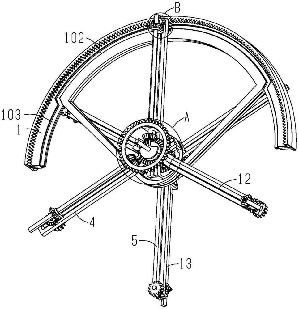
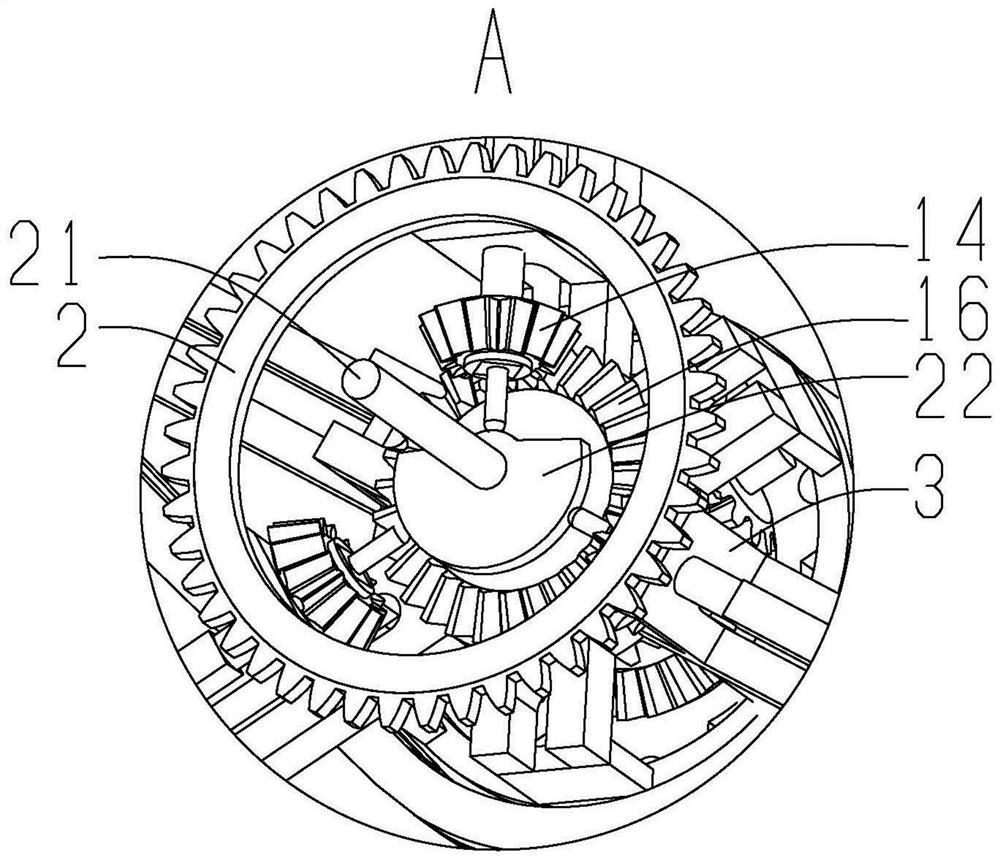
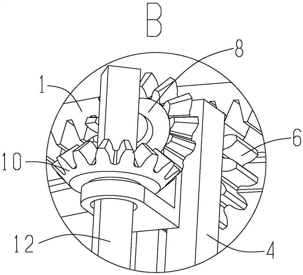
[0044] Please see Figure 1 to Figure 15 , a transmission, including an annular half-gear ring 1, the half-gear ring 1 is not in a fixed position and does not rotate all the time, its front and back inner ring positions are provided with meshing teeth, and its front and back are provided with opposite rings along the circumferential direction. And the same positioning track 101, the middle part of the positioning track 101 is close to the meshing teeth, this section of the positioning track 101 i...


PUM


Abstract

The invention discloses a transmission, and relates to the technical field of transmission equipment. The transmission comprises a half gear ring which is not fixed in position, a transmission disc which is driven by a driver to rotate, first speed changing rails which are fixedly connected to the transmission disc, first power gears which can move along the first speed changing rails and axially rotate, first transmission shafts which are driven by the first power gears to rotate, and a first output gear which is driven by the first transmission shafts to rotate, and the transmission disc, the first speed changing rails, the first power gears and the first transmission shafts are all located on the front face of the half gear ring. The transmission further comprises second transmission rails which are fixedly connected to the transmission disc, second power gears which can move along the second transmission rails and axially rotate, second transmission shafts which are driven by the second power gears to rotate and a second output gear which is driven by the second transmission shafts to rotate, and the transmission disc, the second speed changing rails, the second power gears and the second transmission shafts are all located on the back face of the half gear ring.

Description

technical field [0001] The invention relates to the technical field of transmission equipment, in particular to a transmission. Background technique [0002] The transmission is located between the engine and the running gear, and is used to change the transmission ratio of input and output to realize speed change. Existing speed changer has stepless speed changer, and it is made up of pulley and a metal belt, and pulley is made up of two wheel discs. The continuously variable transmission changes the diameter of the contact between the metal belt and the pulley by narrowing or widening the distance between the wheel discs, so as to achieve different speed conversions. This speed change method results in a relatively small maximum torque and slightly poor stability. Therefore, when the continuously variable transmission is subjected to high-torque power, the requirements for the transmission chain are relatively strict, that is, the transmission chain cannot be broken or s...

Claims


Application Information

Patent Timeline
Patent Type & Authority Applications(China)
IPC IPC(8): F16H3/42
CPCF16H3/42
Inventor 李满仓
Owner 李满仓
Why Eureka
Try Eureka