Feature set and methods for digital positioner

A locator and digital technology, applied in the field of process control systems, can solve the problems of waste movement, waste, unnecessary valves, etc.

Pending Publication Date: 2021-11-26
FISHER CONTROLS INT LLC
View PDF0 Cites 0 Cited by
  • Summary
  • Abstract
  • Description
  • Claims
  • Application Information

AI Technical Summary

Problems solved by technology

For example, the costs associated with providing additional capacity in a fluid supply system can be significant
Additionally, the constant draining of this process medium is costly and environmentally wasteful
A continuous pressure signal throttles the actuator causing unnecessary and wasteful movement of the valve

Method used


Image

  • Feature set and methods for digital positioner
  • Feature set and methods for digital positioner
  • Feature set and methods for digital positioner

Examples


Embodiment Construction

[0031] In order to promote an understanding of the principles of the disclosure, reference will now be made to exemplary embodiments and variations thereof illustrated in the drawings and specific language used to describe the same. It will be understood, however, that no limitation of the scope of the disclosure is thereby intended and that the scope of the disclosure includes such changes in the illustrated devices and Further modifications and such further applications of the principles of the disclosure as illustrated.

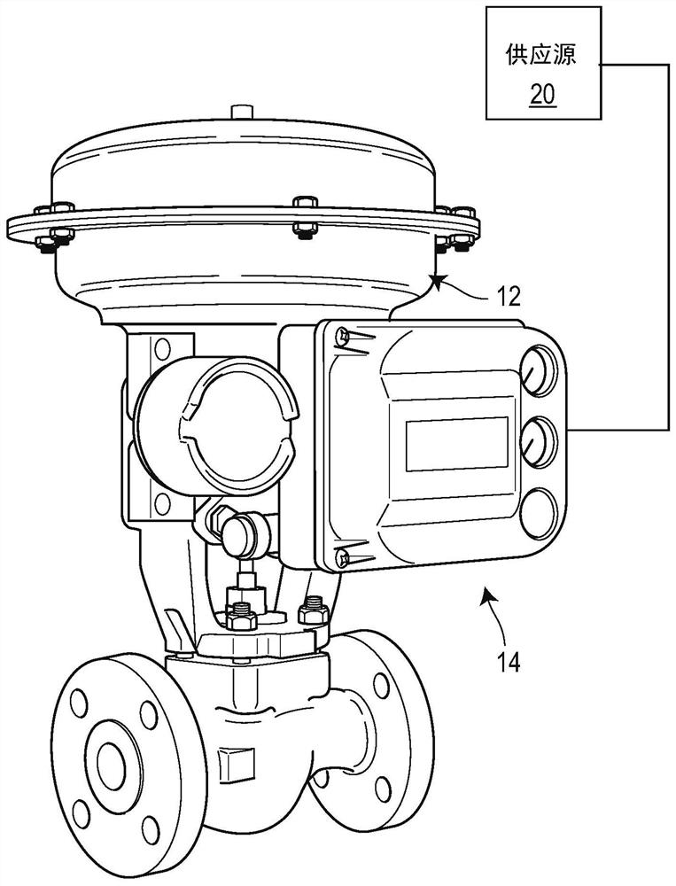
[0032] In general, a digital valve positioner is disclosed for use with an actuator. now refer to figure 1 , depicts an exemplary digital valve positioner 14 mounted to a pneumatic valve actuator 12 (which may also be referred to herein as "actuator 12"). The digital valve positioner 14 includes a valve controller, an I / P module or converter, and a pneumatic relay assembly including a supply relay and a bleed relay. The digital valve positioner 14 gener...


PUM


Abstract

A digital positioner for a valve includes a valve controller configured to obtain a set point value for a valve travel of a valve, and generate a pulse-width modulated current signal based on the set point value. The digital positioner also includes a current-to-pressure converter configured to receive the pulse-width modulated current signal from the valve controller, convert the pulse-width modulated current signal to a pulse-width modulated pressure signal, and provide the pulse-width modulated pressure signal to a pneumatic actuator in the valve to adjust a position of the valve.

Description

technical field [0001] The present disclosure relates to process control systems, and more particularly, to digital positioners for controlling valves in process control systems. Background technique [0002] Industrial process plants use control valves in a variety of applications, from controlling process flow in refineries to maintaining liquid levels in tank farms. Control valves, usually automated, are used to manage this fluid flow by acting like variable orifices or channels. By controlling internal valve components such as the valve plug, the amount of product passing through the valve body can be precisely regulated. The control valve is typically automated using a pressure operated actuator controlled by a remotely operated field instrument, such as a positioner with a valve controller. The valve controller communicates with the process control computer to command changes in the fluid flow within the valve to achieve the control strategy desired by the plant oper...

Claims


Application Information

Patent Timeline
Patent Type & Authority Applications(China)
IPC IPC(8): F16K31/12F16K37/00F15B21/02
CPCF16K31/12F16K37/0083F16K37/0091F15B21/02F04B53/108F15B5/006F15B2211/328F15B2211/329F15B2211/6313F15B2211/6336F15B2211/6656F15B2211/67F15B2211/76F15B2211/7656F15B2211/8855G05B19/46F15B21/087F15B2211/30575H02P29/028H02P29/032H02P27/08
Inventor G·W·加斯曼
Owner FISHER CONTROLS INT LLC
Why Eureka
Try Eureka