CT detector AD array synchronous acquisition method

A technology of synchronous acquisition and detector, applied in instruments, simulators, electrical and digital data processing, etc., can solve the problems of inconsistent path length, reduced number of pins, limitations, etc., so as to reduce the interactive information between two people and improve the stability. , the effect of reducing the restriction

Pending Publication Date: 2021-11-26
FMI MEDICAL SYST CO LTD
View PDF0 Cites 0 Cited by
  • Summary
  • Abstract
  • Description
  • Claims
  • Application Information

AI Technical Summary

Problems solved by technology

For example, the SCK1 generated by the FPGA drives AD#1 to output data at the rising edge, and the FPGA can use the falling edge of SCK1 to collect data. However, this solution occupies a large number of FPGA pins, which limits the ability of an FPGA to drive more ADs.
[0003] another such as figure 2 connection with figure 1 In comparison, the number of FPGA pins consumed is greatly reduced, but because the path lengths from FPGA.SCK to AD#1.SCK and to AD#n.SCK are inconsistent (CS_N, SDI signals are the same), AD#1.SDO to AD#1.SCK The path lengths from FPGA.SDO1 and AD#n.SDO to FPGA.SDOn are inconsistent, which causes the delays of all FPGA input pins SDO1, SDO2...SDOn to the same FPGA output pin SCK to be inconsistent. At this time, use the same A SCK sampling all input data may not find a suitable sampling window, such as image 3 shown
In order to solve this problem, the existing method is to require all the above-mentioned connections to be of the same length when wiring the circuit board, but this is limited by the space layout and wiring of the circuit board in actual operation. More AD capabilities

Method used


Image

  • CT detector AD array synchronous acquisition method
  • CT detector AD array synchronous acquisition method
  • CT detector AD array synchronous acquisition method

Examples


Embodiment Construction

[0020] refer to Figure 1 to Figure 5 A specific implementation of a method for synchronous acquisition of a CT detector AD array in the present invention will be further described.

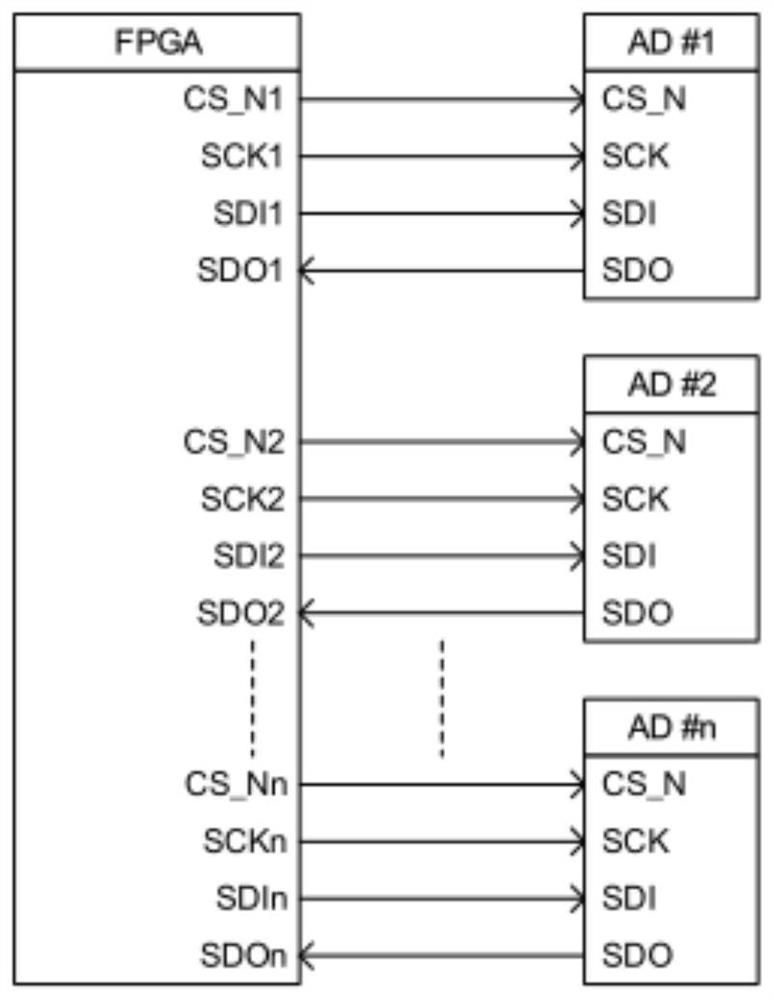
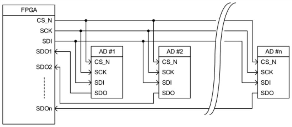
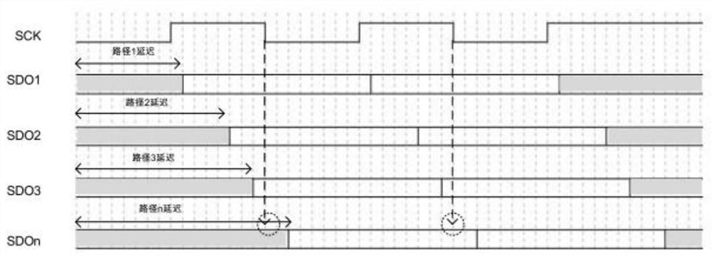
[0021] A method for synchronous acquisition of a CT detector AD array, including an SCK master clock, the SCK master clock outputs signals to drive the AD array, and the SCK master clock generates a number of clocks with the same frequency but different phases through an on-chip PLL. In the embodiment, clocks with 8 phases at equal intervals of 22.5° are generated. In different specific products, clocks with higher density and different phases can be generated by cascading on-chip PLLs according to the actual situation. The specific workflow of the synchronization state machine as follows:

[0022] (1) The synchronization state machine is started, and the control training command generator uses CS_N, SDI to send a command that can return a fixed value to the AD array, such as reading the version...


PUM


Abstract

The invention discloses a CT detector AD array synchronous acquisition method. According to the method, an SCK main clock is included and outputs a signal to drive an AD array, the SCK main clock generates a plurality of clocks with the same frequency and different phases through a PLL in a chip, and each channel acquires an input signal by using a respective locked clock, carries out clock domain crossing on the acquired data, and unifies in the SCK main clock domain forsubsequent processing. According to the invention, a sampling window of each input data line can be automatically found, and the limitation of basic manufacturing and layout wiring is reduced, so that one FPGA can drive more AD, the cost can be reduced, the information of interaction between every two FPGAs can be reduced, and the stability of a system is improved.

Description

technical field [0001] The invention relates to the technical field of tomographic scanning medical equipment, and more specifically relates to a method for synchronous acquisition of an AD array of a CT detector. Background technique [0002] Among AD chips suitable for CT detectors, the data readout interface of a type of AD chip is an SPI interface. An SPI interface usually has 4 signal lines. In a detector, hundreds of the same ADs are required to form a whole column. These ADs all need FPGAs to control them and collect data. How to use as few FPGAs as possible to control more ADs can not only reduce the cost, but also reduce the information exchanged between FPGAs and improve the stability of the system. There are two ways of hardware connection between FPGA and AD array to deal with this problem in the prior art, one such as figure 1 As shown in , the pins of each AD chip correspond to the pins of the FPGA one by one. The advantage of this is that the SCK and SDO of...

Claims


Application Information

Patent Timeline
IPC IPC(8): G06F13/40G06F13/42G05B19/042
CPCG06F13/405G06F13/4291G05B19/0423
Inventor 陈修儒黄振强贺崇煊余李
Owner FMI MEDICAL SYST CO LTD
Why Eureka
Try Eureka