Method for calculating turbulence intensity of tail flow of wind turbine

A technology of turbulence intensity and calculation method, which is applied in the field of accurate and fast calculation of wind turbine wake turbulence intensity, and can solve the problems of low calculation model dimension, cumbersome calculation process, and affecting the universality of model application

Pending Publication Date: 2021-11-26
NANJING UNIV OF AERONAUTICS & ASTRONAUTICS
View PDF1 Cites 2 Cited by
  • Summary
  • Abstract
  • Description
  • Claims
  • Application Information

AI Technical Summary

Problems solved by technology

However, the existing engineering models still have the following problems: (1) Most of the models are limited to predicting the maximum turbulence intensity in the wake area of ​​the wind turbine. It is believed that the turbulence intensity in the wake area only changes with the flow distance x, is a constant, that is, a one-dimensional model
However, the Jensen wake radius model assumes that the wind turbine wake expands linearly downstream and expands wirelessly at infinity, which is seriously inconsistent with the actual situation; (3) for the few 3D models proposed recently (Ishihara T, Qian G W .Anew Gaussian-based analytical wake model for wind turbines considering ambient turbulence intensities and thrust coefficient effects[J].Journal of Wind Engineering and Industrial Aerodynamics,2018,177:275-292.; Chinese patent

Method used


Image

  • Method for calculating turbulence intensity of tail flow of wind turbine
  • Method for calculating turbulence intensity of tail flow of wind turbine
  • Method for calculating turbulence intensity of tail flow of wind turbine

Examples


Embodiment 1

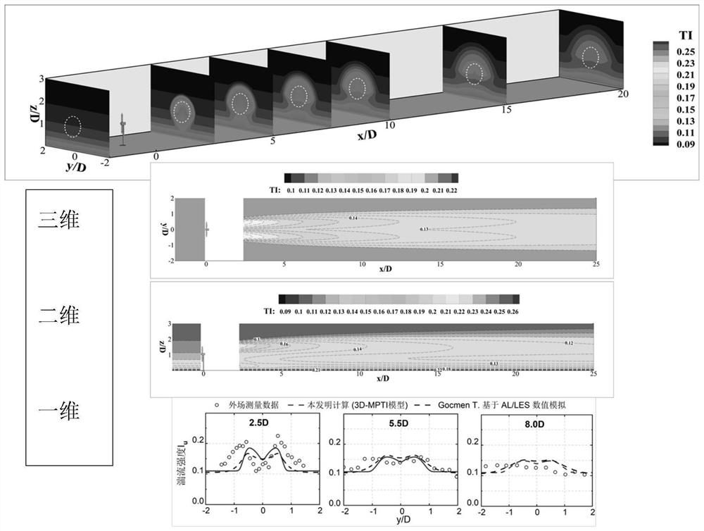
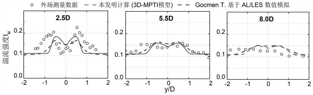
[0050] The Sexbierum wind farm contains 18 units with a rated power of 310kW, the diameter of the wind rotor D=30m, and the hub height z hub = 35m unit, installed multiple anemometers to measure the wake field and power generation of single and multiple units. For the wake test of a single wind turbine, three typical locations downstream of the unit at 2.5D, 5.5D and 8.0D (including three types of near wake, transitional wake and far wake) are the main measurement objects. Select the wind speed U at the hub height position of the incoming flow 0,hub =8.4m / s, turbulence intensity I 0,hub =10% is the test condition (the corresponding wind profile exponent power α=0.15, surface roughness z 0 =0.078m, wind turbine thrust coefficient Ct=0.75), the turbulence intensity distribution in the wake area of ​​the wind turbine is predicted for it, and the specific steps are as follows:

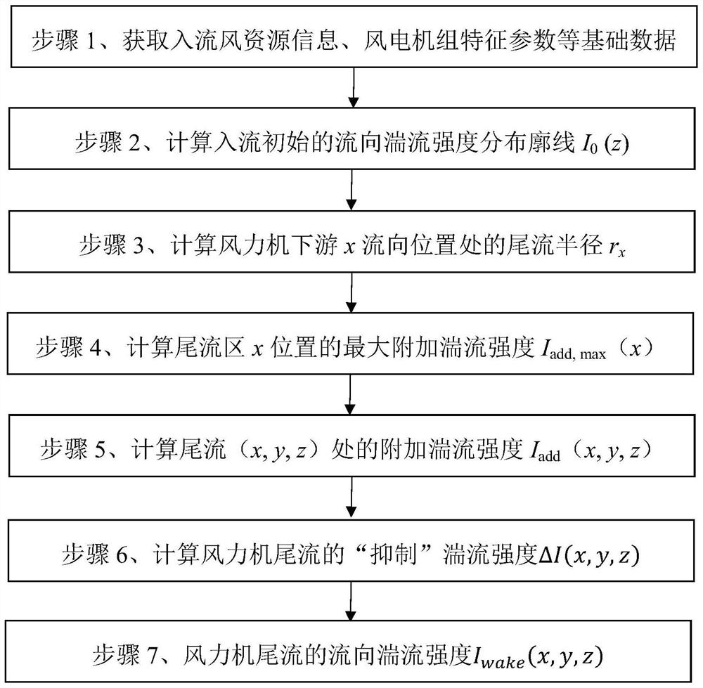
[0051] (1) Confirm basic data such as inflow wind resource information and characteristic parameters...

Embodiment 2

[0072] In 2009, Chamorro et al. (Chamorro, L.P.; Porté-Agel, F.A wind-tunnel investigation of wind-turbine wakes: Boundary-layer turbulence effects. Bound. Layer Meteorol. 2009, 132, 129–149) carried out wind tunnel experiments on wind turbine wakes Research. The experimental object is a WiRE EP-6030 wind turbine, the diameter of the wind rotor is D=0.15m, and the height of the hub is z hub =0.125m, mainly observe the distribution of flow variables at the downstream (x / D=3,5,7,10,14,20) equi-section positions. The incoming flow condition is the wind speed U at the height of the hub 0,hub =2.2m / s, turbulence intensity I 0,hub =7.0% (at this time, the corresponding wind profile exponent power α=0.15, surface roughness z 0 =2.5×10 -5 m, wind turbine thrust coefficient Ct=0.56). The distribution of the turbulence intensity distribution in the wake of the wind turbine is predicted for this working condition.

[0073]The calculation steps used in this embodiment are the same a...

Embodiment 3

[0075] In 2015, Troldborg et al. (Trldborg N, J An improved k-e modelapplied to a wind turbine wake in atmospheric turbulence.2015,18:889-907) carried out a high-precision numerical simulation of the wake of a single NREL 5MW wind turbine using the AD / LES method. Wind wheel diameter D = 126m, hub height z hub = 90m, mainly focus on downstream (x / D=2.5, 5 and 7.5) equal sections. Incoming flow hub height position wind speed U 0,hub =8.0m / s, turbulence intensity I 0,hub =4.0% (at this time, the corresponding wind profile exponent power α=0.10, and the thrust coefficient Ct of the wind turbine=0.79). The distribution of the turbulence intensity distribution in the wake of the wind turbine is predicted for this working condition.

[0076] The calculation steps adopted in this embodiment are the same as those in Embodiment 1, and the calculated distribution of turbulence intensity along the y direction at three typical positions is as follows: Figure 7 As shown, it can be se...


PUM

PropertyMeasurementUnit
Heightaaaaaaaaaa

Abstract

The invention discloses a method for calculating the turbulence intensity of the tail flow of a wind turbine. The method comprises the following steps: calculating a flow direction turbulence intensity vertical direction distribution type of inflow, a wake flow radius at any flow direction cross section position of a wake flow area and maximum additional turbulence intensity generated by a wake flow effect based on basic data such as inflow wind resource information and wind turbine generator characteristic parameters; calculating the additional turbulence intensity and the 'inhibition' turbulence intensity of the wake flow area position; and calculating the flow direction turbulence intensity of any position of the tail flow of the wind turbine based on the steps. According to the method, the flow direction turbulence intensity of any spatial position can be predicted with high precision, especially the 'double-peak' distribution of the near wake flow turbulence intensity and the 'turbulence weakening' effect of the near ground position, and the prediction precision is superior to that of a numerical simulation result based on computational fluid mechanics. And an accurate and efficient turbulence calculation tool is provided for wind turbine design and wind power plant unit layout optimization in a wind engineering project.

Description

technical field [0001] The invention belongs to the technical field of new energy wind power generation, and in particular relates to an accurate and fast calculation method for wake turbulence intensity of a wind turbine, which can be used for wind engineering projects such as wind turbine design and wind farm micro site selection. Background technique [0002] After the wind flows through the wind turbine, it forms a wake downstream, and then expands and meanders longitudinally and vertically, and finally dissipates in an almost chaotic manner. The wake structure of wind turbines is complex, including multi-scale coupled vortex systems such as blade tip vortex, blade root vortex, and hub vortex, resulting in severe airflow disturbance and increased turbulence intensity in the wake area. Turbulence intensity is an important factor affecting the fatigue load and ultimate load of wind turbines, and has become one of the important parameters of IEC61400-1 wind turbine safety c...

Claims


Application Information

Patent Timeline
IPC IPC(8): G06F30/28G06F113/06G06F113/08G06F119/14
CPCG06F30/28G06F2113/08G06F2119/14G06F2113/06
Inventor 田琳琳赵宁肖鹏程宋翌蕾王同光
Owner NANJING UNIV OF AERONAUTICS & ASTRONAUTICS
Why Eureka
Try Eureka