
Centrifugal separation pipe, gas-liquid separation device and refrigerating system with device

A technology of gas-liquid separation device and centrifugal separation tube, which is applied in the direction of refrigerators, refrigeration components, separation methods, etc., can solve the problems of increasing the complexity of refrigeration systems, reducing the refrigeration efficiency of refrigerants, and flashing gases of refrigerants, etc., to achieve improved Gas-liquid separation efficiency, improve refrigeration efficiency, and realize the effect of gas-liquid separation

Pending Publication Date: 2021-11-30
TAIZHOU LONGJIANG CHEM MACHINERY TECH
View PDF7 Cites 0 Cited by
  • Summary
  • Abstract
  • Description
  • Claims
  • Application Information

AI Technical Summary

Problems solved by technology

[0003] The refrigerant liquid at room temperature and high pressure must be throttled before entering the gas-liquid separator. The liquid refrigerant after throttling is cooled and depressurized. , the temperature of the refrigerant will increase slightly when throttling, resulting in flash gas of the refrigerant during throttling, which reduces the cooling efficiency per unit of refrigerant
Usually, in order to reduce the flash gas when the refrigerant liquid is throttling, an economizer, a subcooler and other equipment are added to the refrigeration system, but the complexity of the refrigeration system is increased due to the addition of equipment, and the pipelines of the refrigeration system are also increased. Valves, Instruments, etc.

Method used


Image

  • Centrifugal separation pipe, gas-liquid separation device and refrigerating system with device
  • Centrifugal separation pipe, gas-liquid separation device and refrigerating system with device
  • Centrifugal separation pipe, gas-liquid separation device and refrigerating system with device

Examples


Embodiment Construction

[0031] In order to facilitate the understanding of those skilled in the art, the present invention will be further described below in conjunction with the embodiments and accompanying drawings, and the contents mentioned in the embodiments are not intended to limit the present invention.

[0032] In the prior art, for example, a helical tube gas-liquid separation device disclosed in application number 201310621926.8 is provided with a helical tube coaxial with the cylinder, the top of the helical tube is a gas-liquid mixing inlet, and the bottom is a liquid outlet. The principle of the gas-liquid separation of the spiral tube is: after the gas-liquid mixed fluid to be separated enters the spiral tube from the upper end, it will rotate at a high speed under the action of pressure and flow rate. Due to the different densities of the gas and liquid, the liquid will fall faster. , the gas rises, so that the gas and liquid are separated. In this technology, the gas separated from g...


PUM


Abstract

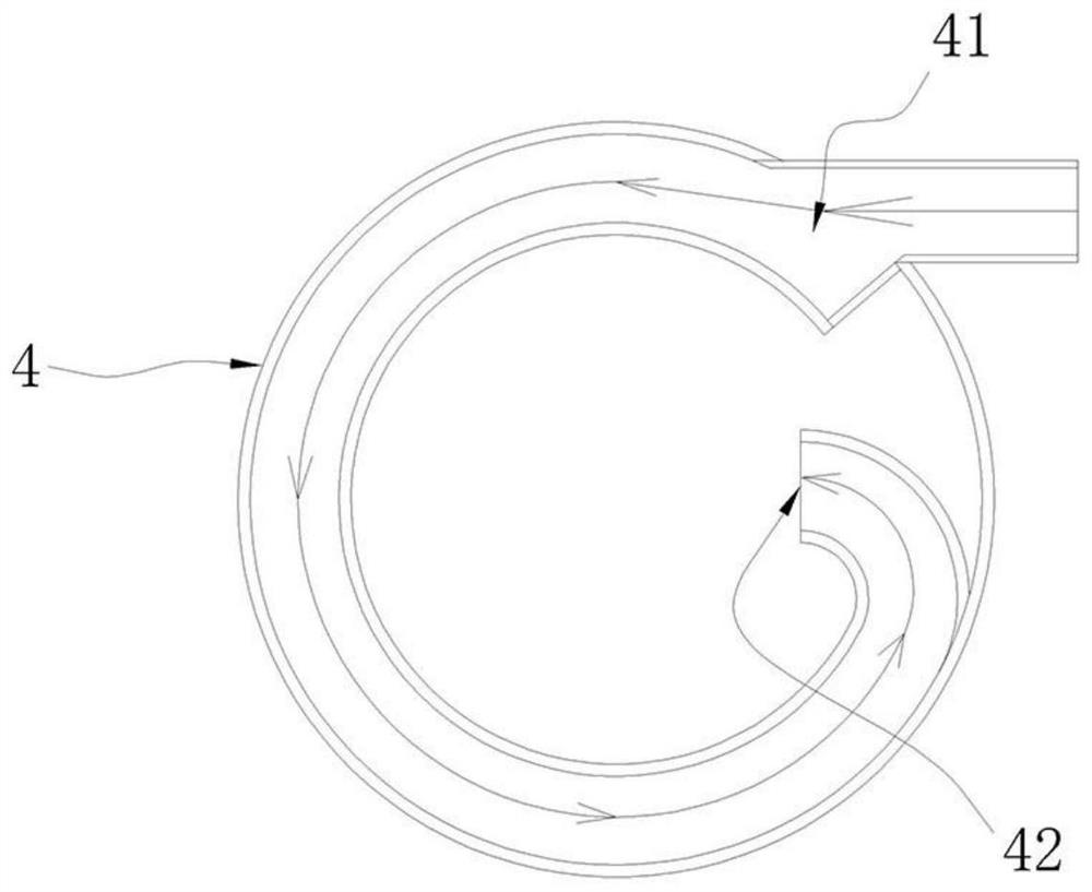
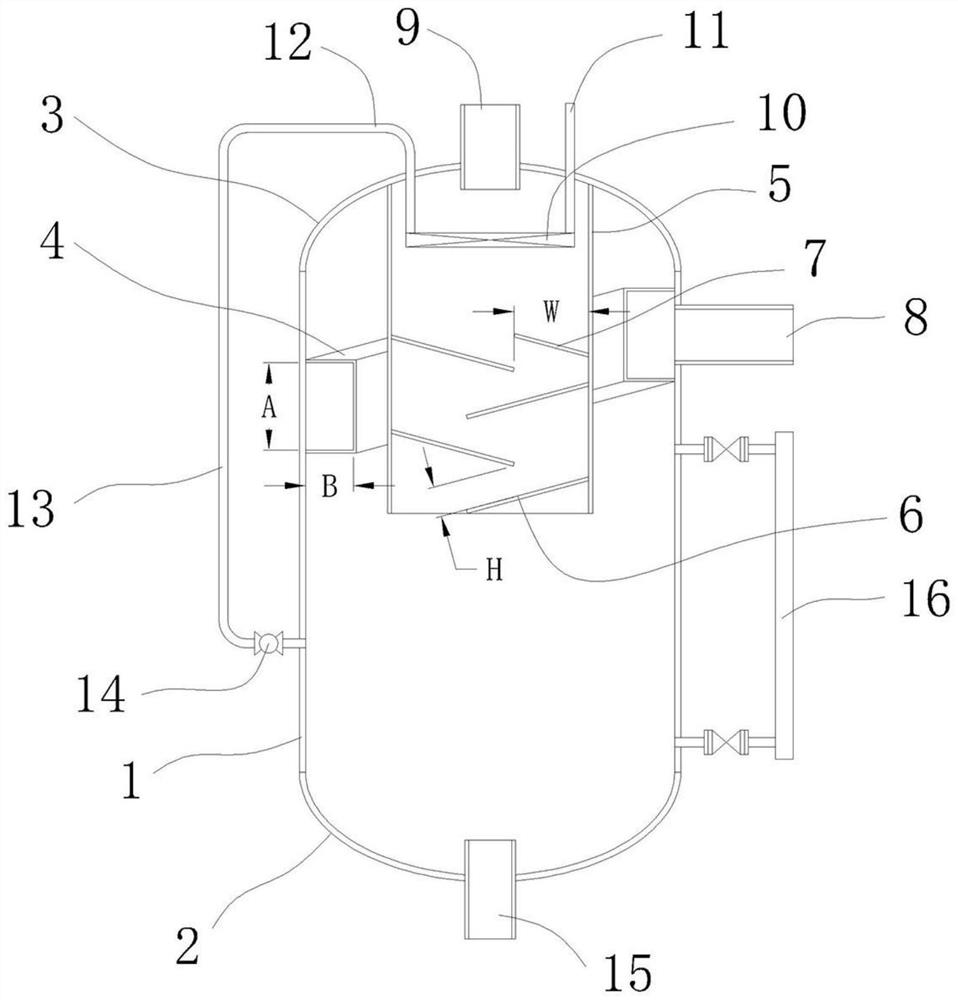
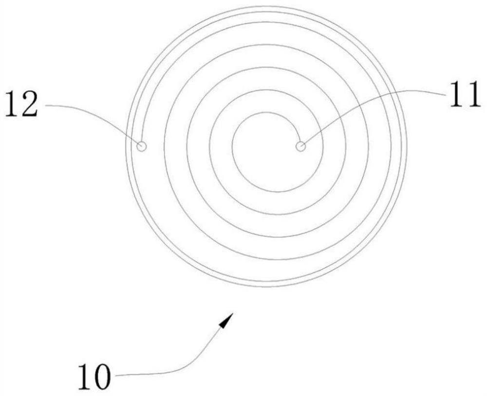
The invention discloses a centrifugal separation pipe, a gas-liquid separation device and a refrigerating system with the device. The centrifugal separation pipe comprises a spiral pipe body, the inlet end of the pipe body is higher than the outlet end, the centrifugal separation pipe is characterized in that the section of the pipe body is rectangular, the extending direction of the inlet end is located in the tangential direction of the pipe body; the outlet end is bent in the direction of the spiral axis and right faces the axis. The centrifugal separation pipe can conduct effective gas-liquid separation on fluid through the rectangular pipe body. According to the gas-liquid separation device, a centrifugal separation pipe, a flow guide component and a heat exchange component are used for carrying out gas-liquid separation on fluid for multiple times, and the gas-liquid separation effect is improved; after the gas-liquid separation device is adopted by the refrigerating system, the refrigerating efficiency can be greatly improved.

Description

technical field [0001] The invention belongs to the technical field of refrigeration and relates to a gas-liquid separation technology, in particular to a centrifugal separation tube, a gas-liquid separation device and a refrigeration system with the device. Background technique [0002] Most of the compressors used in the refrigeration system are displacement compressors, such as piston compressors and screw compressors. The low-temperature and low-pressure refrigerant gas is compressed into high-temperature and high-pressure refrigerant gas after consuming mechanical work in the compressor. Then in the condenser, the normal temperature and high pressure refrigerant liquid is condensed. If there is still liquid in the gas sucked by the compressor, the liquid will rapidly vaporize after absorbing heat in the compression cavity of the compressor. Since the volume of the refrigerant gas per unit mass is several times that of the liquid, the volume of the refrigerant expands ra...

Claims


Application Information

Patent Timeline
IPC IPC(8): B01D45/16F25B43/00
CPCB01D45/16F25B43/00
Inventor 熊从贵何静林通宋玲丽金琦林家锋夏冬冬
Owner TAIZHOU LONGJIANG CHEM MACHINERY TECH
Learn More