Rainwater recycling type catch basin structure

A technology of reuse and shape rain, applied in the field of rainwater inlets, can solve the problems of inability to purify rainwater, waste of rainwater resources, etc., and achieve the effects of improving cleanliness, realizing recycling and reuse, and improving service life.

Active Publication Date: 2021-11-30
江苏晟益建筑安装工程有限公司
View PDF11 Cites 1 Cited by
  • Summary
  • Abstract
  • Description
  • Claims
  • Application Information

AI Technical Summary

Problems solved by technology

[0003] However, the rainwater wells in the current related technologies only have the function of collecting and discharging rainwater, and cannot purify rain

Method used


Image

  • Rainwater recycling type catch basin structure
  • Rainwater recycling type catch basin structure
  • Rainwater recycling type catch basin structure

Examples


Embodiment 1

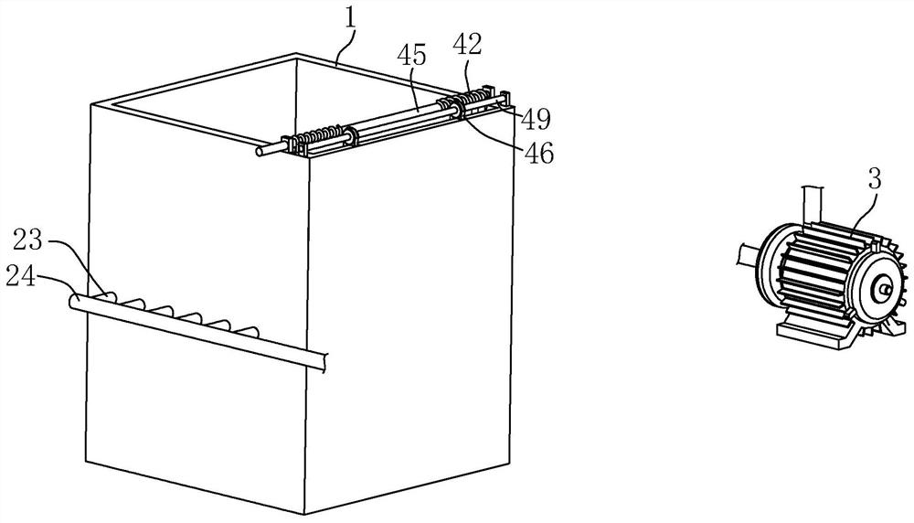
[0038] The embodiment of the present application provides a rainwater reuse type rainwater well structure, referring tofigure 1 and figure 2 , including a water inlet pipe 1 and a filter assembly 2, the water inlet pipe 1 is a square tube with an open top, and the filter assembly 2 is connected in the water inlet pipe 1.

[0039] The rainwater enters the water inlet pipe 1, and the filter assembly 2 filters the rainwater, so as to filter impurities in the rainwater and improve the purity of the rainwater. The purified rainwater flows into the municipal pipeline through the rainwater distribution pipe 3 .

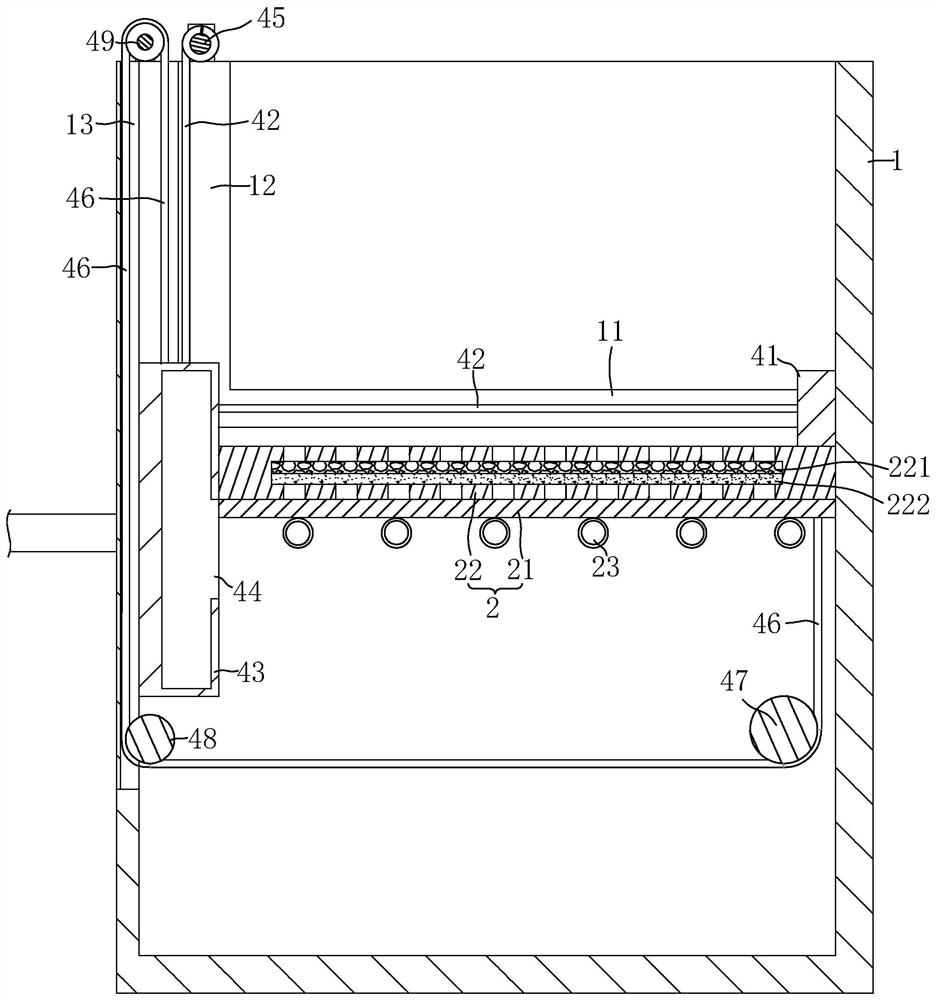
[0040] refer to figure 2 , the filter assembly 2 includes a support plate 21 and a filter box 22, the support plate 21 is a steel grating, and is horizontally fixedly connected in the water inlet pipe 1, the filter box 22 is placed on the support plate 21, and its outer wall is attached to the water inlet pipe 1 inner wall. The upper surface and the lower surface of the...

Embodiment 2

[0049] The difference between the embodiment of the present application and embodiment 1 is that, referring to Figure 4 , The rainwater reuse type rainwater well structure also includes a pressure-type drainage component 5, a sedimentation water purification component 6 and a water storage tank 7.

[0050] refer to Figure 4 , The pressure-type water assembly 5 includes a water receiving box 51 , a pressure plate 52 , a sealing ring 53 , a collision platform 54 and a pressure spring 55 . The water receiving box 51 is fixedly connected below the water inlet pipeline 1, and the top of the water receiving box 51 is open. The sealing ring 53 is fixedly connected in the water inlet pipe 1 and has a rectangular area inside, and the sealing ring 53 is located under the support plate 21 . The pressure receiving plate 52 is located in this rectangular area. The inner wall of the sealing ring 53 is stepped, and the outer wall of the pressure receiving plate 52 is stepped to engage w...


PUM


Abstract

The invention relates to catch basins, and discloses a rainwater recycling type catch basin structure. The rainwater recycling type catch basin structure comprises a water inlet pipeline and a filtering assembly, the filtering assembly is connected into the water inlet pipeline and comprises a supporting plate and a filtering box, the supporting plate is horizontally and fixedly connected into the water inlet pipeline, and the filtering box is placed on the supporting plate; and a backwashing pipe is fixedly connected to the lower surface of the supporting plate, a plurality of water outlet holes facing the filtering box are formed in the pipe wall of the backwashing pipe, the backwashing pipe penetrates through the side wall of the water inlet pipeline and communicates with a water inlet header pipe, one end of the water inlet header pipe is closed, and the other end of the water inlet header pipe communicates with a water suction pump. Through the arrangement of the filtering assembly, impurities in rainwater are filtered, so that the effect of purifying water is achieved, and recycling of the rainwater is achieved.

Description

technical field [0001] The invention relates to a rainwater outlet, in particular to a rainwater reuse type rainwater well structure. Background technique [0002] A rainwater well is a pipe used to collect rainwater. It can infiltrate rainwater into the ground, and the excess rainwater can be drained through other pipes to collect and discharge rainwater well during the rainy season. [0003] However, the rainwater wells in the current related technologies only have the function of collecting and discharging rainwater, and cannot purify rainwater. As a kind of water resource, rainwater has great potential for resource reuse. If it is not purified, it will inevitably be destroyed. Waste of rainwater resources. Contents of the invention [0004] In order to realize the recovery and reuse of rainwater, the present application provides a rainwater reuse type rainwater well structure. [0005] An edge suction device adjustment frame provided by this application adopts the fo...

Claims


Application Information

Patent Timeline
IPC IPC(8): C02F9/02
CPCC02F9/00C02F1/001C02F1/28C02F1/52C02F2103/001C02F2303/14C02F2303/16Y02A20/108
Inventor 周坚
Owner 江苏晟益建筑安装工程有限公司
Why Eureka
Try Eureka