Combined sand box unloading device

An unloading device and combined technology, applied in excavation, construction, infrastructure engineering, etc., can solve the problems of unbalanced force on the device, injury to construction personnel, overload damage of the unloading device, etc., to achieve high synchronization control accuracy and improve work efficiency. Efficiency and security effect

Pending Publication Date: 2021-11-30
厦门安捷建筑工程有限公司
View PDF0 Cites 0 Cited by
  • Summary
  • Abstract
  • Description
  • Claims
  • Application Information

AI Technical Summary

Problems solved by technology

For the brace structure and corner brace structure in the steel structure support system, when the foundation work is completed and the support needs to be dismantled forcibly, the huge support pressure will be released suddenly, which may cause support members or building material fragments to jump up, injuring construction personnel or smash other objects
In order to avoid accidents, it is common practice to use an unloading device at present. The existing unloading device adopts a single-cylinder sand box unloading device, which has the following disadvantages: 1) The steel structure has a large support pressure and requires multiple single-cylinder sand boxes. The box unloading device is used at the same time, and the synchronous control accuracy is low, resulting in unbalanced force on the device, and may even cause overload damage to the unloading device; 2) The cost of multiple single sand box devices is high

Method used


Image

  • Combined sand box unloading device
  • Combined sand box unloading device
  • Combined sand box unloading device

Examples


Embodiment 1

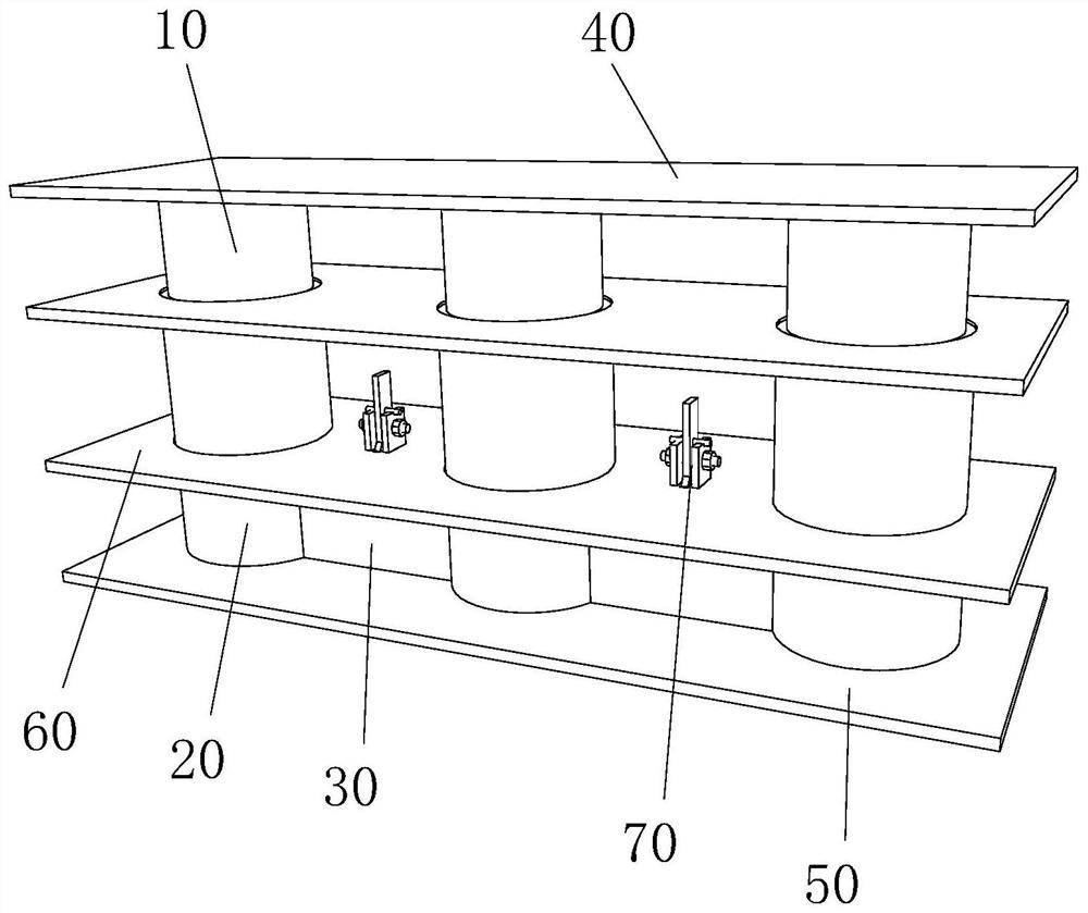
[0034] like Figure 1-3 As shown, the bottom of the sleeve 20 is fixedly connected to the second support plate 50, preferably by welding, for higher reliability. The inside of the sleeve 20 forms a cavity, and an opening for inserting the piston 10 is provided at the top of the sleeve 20 . The sleeves 20 are connected through the connecting channel 30 to form an internal space for containing sand particles. Specifically, the sleeves 20 are arranged side by side on the second support plate 50, and the adjacent sleeves 20 are connected through the connecting channel 30. And the bottom of the connecting channel 30 is also fixedly connected with the second support plate 50, the connecting channel 30 can also play a stabilizing effect on the sleeve 20, and at the same time, the bottom surface of the connecting channel 30 can be flush with the bottom surface of the sleeve 20 or tend to In this way, it can be ensured that when unloading, the sand particles in the inner space always ...

Embodiment 2

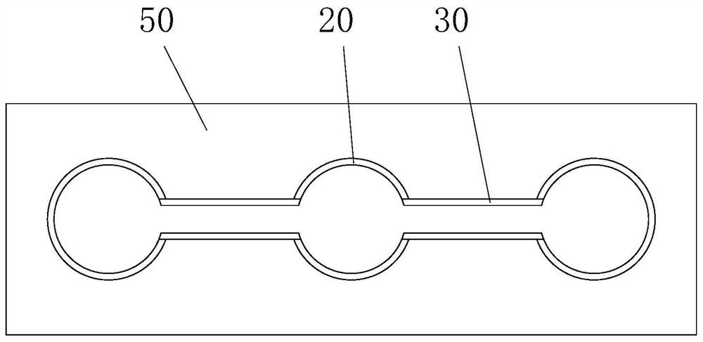
[0041] like Figure 4-5 As shown, as another preferred embodiment, the difference between this embodiment and Embodiment 1 is that the sleeves 20 are arranged in the shape of an equilateral triangle, and this arrangement is suitable for a single larger support point or relatively concentrated multiple support points situation.

[0042] When the number of sleeves 20 is more than three, except for the case where the sleeves 20 are arranged side by side, connecting passages 30 can be provided between any two sleeves 20 to utilize synchronous control. In a word, the number and arrangement of the sleeves 20 of the present invention are designed according to the stress and cross-sectional shape of the support structure of the foundation pit, but the basic principles are interoperable.

[0043] When the present invention is in use, it is directly installed on the support of the foundation pit, and the support bears huge pressure. Of course, this pressure also acts on the sand box un...


PUM


Abstract

The invention relates to a combined sand box unloading device. The combined sand box unloading device comprises at least two sleeves, pistons in one-to-one correspondence with the sleeves, at least one sand discharging valve, a first supporting plate and a second supporting plate; the bottoms of the sleeves are fixedly connected with the second supporting plate, and the sleeves communicate with each other through a connecting channel to form an inner space used for containing sand grains; the tops of the pistons are fixedly connected with the first supporting plate; the pistons are inserted into the sleeves and slidably connected with the sleeves; and sand discharging openings are formed in the sleeves and / or the channels, and the sand discharging valves are matched with the sand discharging openings to complete sand discharging operation. The sleeves communicate with the second supporting plate to form a whole through the connecting channel and used for containing the sand grains, and the contained sand grains can be kept at the same height under the action of the pistons and external supporting pressure, so that the synchronous control precision of the device is high and stress of all supporting points is balanced; and the sand grains are discharged through the sand discharging valves, so that the pistons and the first supporting plate slowly move towards the second supporting plate, the foundation pit steel structure support is conveniently unloaded, the safety of support dismounting work is guaranteed, and the working efficiency is improved.

Description

technical field [0001] The invention relates to the technical field of steel structures, in particular to a combined sand box unloading device. Background technique [0002] Foundation pit support is a key project to ensure the safety of high-rise building foundation pit engineering. Steel structure support is widely used because of its economical applicability, convenient construction, energy saving and environmental protection. For the brace structure and corner brace structure in the steel structure support system, when the foundation work is completed and the support needs to be dismantled forcibly, the huge support pressure will be released suddenly, which may cause support members or building material fragments to jump up, injuring construction personnel or damage other objects. In order to avoid accidents, it is common practice to use an unloading device at present. The existing unloading device adopts a single-cylinder sand box unloading device, which has the follow...

Claims


Application Information

Patent Timeline
IPC IPC(8): E02D17/04
CPCE02D17/04
Inventor 李荷英吕银建王煤华彭兴黔何庆杉
Owner 厦门安捷建筑工程有限公司
Why Eureka
Try Eureka