Object processing method and device and computer readable storage medium

A processing method and computer program technology, applied in the computer field, can solve the problems of wall reflection and unclear captured images, and achieve the effect of clear image data.

Pending Publication Date: 2021-11-30
PEKING UNIV
View PDF3 Cites 0 Cited by
  • Summary
  • Abstract
  • Description
  • Claims
  • Application Information

AI Technical Summary

Problems solved by technology

[0004] Embodiments of the present invention provide an object processing method, device, and computer-readable storage medium, so as to at least solve the technical problem in the related art that when an image is captured of particles in a flow field, reflections on the wall appear and the captured image is not clear

Method used


Image

  • Object processing method and device and computer readable storage medium
  • Object processing method and device and computer readable storage medium
  • Object processing method and device and computer readable storage medium

Examples


Embodiment 1

[0026] According to an embodiment of the present invention, an embodiment of an object processing method is provided. It should be noted that the steps shown in the flowcharts of the drawings can be executed in a computer system such as a set of computer-executable instructions, and, although A logical order is shown in the flowcharts, but in some cases the steps shown or described may be performed in an order different from that shown or described herein.

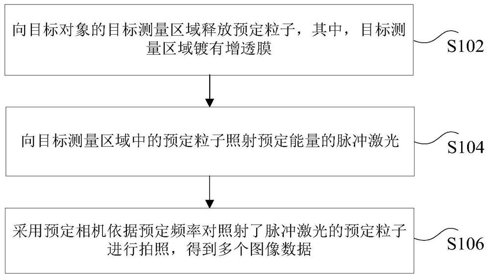
[0027] figure 1 is an object processing method according to an embodiment of the present invention, such as figure 1 As shown, the method includes the following steps:

[0028] Step S102, releasing predetermined particles to the target measurement area of ​​the target object, wherein the target measurement area is coated with an anti-reflection film;

[0029] Step S104, irradiating the predetermined particles in the target measurement area with pulsed laser light of predetermined energy;

[0030] Step S106, using a pred...

Embodiment 2

[0059] According to an embodiment of the present invention, a device for implementing the above object processing method is also provided, Figure 4 is a structural block diagram of an object processing device according to an embodiment of the present invention, such as Figure 4 As shown, the device includes: a first control module 402, a second control module 404 and a camera module 406, and the device will be described in detail below.

[0060] The first control module 402 is used to release predetermined particles to the target measurement area of ​​the target object, wherein the target measurement area is coated with an anti-reflection film; the second control module 404 is connected to the above-mentioned first control module 402 and is used to measure the particles to the target Predetermined particles in the area are irradiated with pulsed laser light of predetermined energy; the photographing module 406 is connected to the above-mentioned second control module 404, an...

Embodiment 3

[0063] In an exemplary embodiment, there is also provided a computer-readable storage medium including instructions, and when the instructions in the computer-readable storage medium are executed by a processor of the terminal, the terminal is able to perform any one of the above-mentioned object processing methods . Alternatively, the computer-readable storage medium may be a non-transitory computer-readable storage medium, for example, the non-transitory computer-readable storage medium may be ROM, random access memory (RAM), CD-ROM, magnetic tape, floppy disk, and optical data storage medium. storage devices, etc.

[0064] Optionally, in this embodiment, the above-mentioned computer-readable storage medium may be used to store the program code executed by the object processing method provided by the above-mentioned embodiment.

[0065] Optionally, in this embodiment, the above-mentioned computer-readable storage medium may be located in any computer terminal in the group o...


PUM


Abstract

The invention discloses an object processing method and device and a computer readable storage medium. The method comprises the steps of releasing predetermined particles to a target measurement area of a target object, wherein the target measurement area is plated with an antireflection film, irradiating pulse laser with predetermined energy to the predetermined particles in the target measurement area, and photographing the predetermined particle irradiated with the pulse laser by using a predetermined camera according to a predetermined frequency to obtain a plurality of image data. The technical problem that the shot image is not clear due to wall reflection when the image of the particles in the flow field is shot in the prior art is solved.

Description

technical field [0001] The present invention relates to the field of computers, in particular to an object processing method, device and computer-readable storage medium. Background technique [0002] In related technologies, when the conventional Tomo-PIV (Tomographic Partivle Image Velocimetry, tomographic particle image velocimetry technology) measures the velocity field of particles in the near-wall flow field of a three-dimensional curved surface, since the light source illuminates the curved surface, the reflection interference formed by the curved surface covers up the flow field. The optical signal information of the particle image of the field makes it impossible to calculate the particle velocity field in the three-dimensional curved surface near-wall flow field. [0003] For the above problems, no effective solution has been proposed yet. Contents of the invention [0004] Embodiments of the present invention provide an object processing method, device, and com...

Claims


Application Information

Patent Timeline
Patent Type & Authority Applications(China)
IPC IPC(8): G01P5/00G01P5/20G06T17/00
CPCG01P5/001G01P5/20G06T17/00
Inventor 朱一丁
Owner PEKING UNIV
Why Eureka
Try Eureka