Laser cutting machine for workpiece hole site

A laser cutting machine, laser cutting technology, applied in the direction of laser welding equipment, manufacturing tools, metal processing equipment, etc., to achieve the effect of cost saving

Pending Publication Date: 2022-01-28
GBOS LASER INC
View PDF1 Cites 0 Cited by
  • Summary
  • Abstract
  • Description
  • Claims
  • Application Information

AI Technical Summary

Problems solved by technology

Although this prior art provides the application of the CCD camera to take pictures at the bottom of the workpiece, the main technical problem to be solved is to adjust the cutting parameters of the laser correspondingly by observing the cutting depth of the laser.

Method used


Image

  • Laser cutting machine for workpiece hole site
  • Laser cutting machine for workpiece hole site
  • Laser cutting machine for workpiece hole site

Examples


Embodiment Construction

[0029]In order to make the object, technical solution and advantages of the present invention clearer, the present invention will be described and illustrated below in conjunction with the accompanying drawings and embodiments. It should be understood that the specific embodiments described here are only used to explain the present invention, not to limit the present invention. Based on the embodiments provided by the present invention, all other embodiments obtained by persons of ordinary skill in the art without creative efforts fall within the protection scope of the present invention. In addition, it is also understood that although such development efforts may be complex and lengthy, for those of ordinary skill in the art relevant to the content of the present disclosure, the technology disclosed in the present invention Some design, manufacturing or production changes based on the content are just conventional technical means, and should not be understood as insufficient...


PUM


Abstract

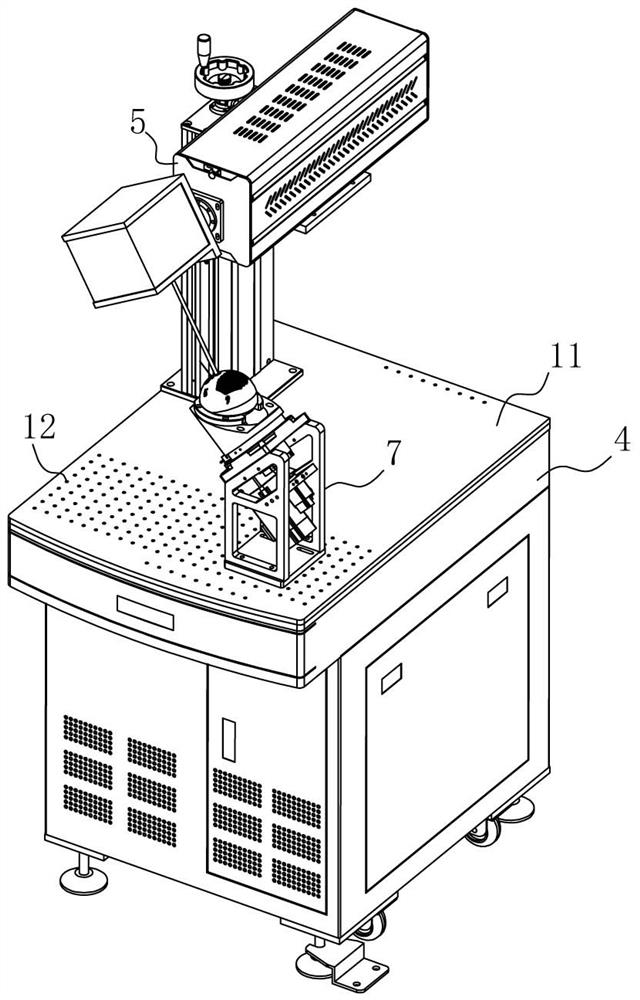
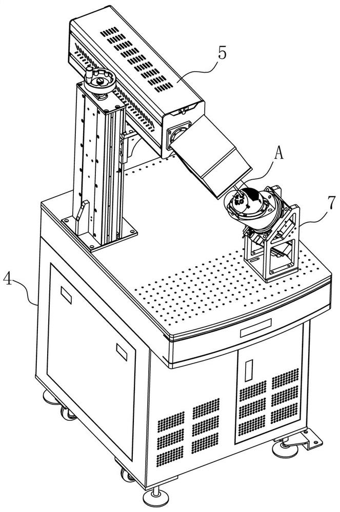
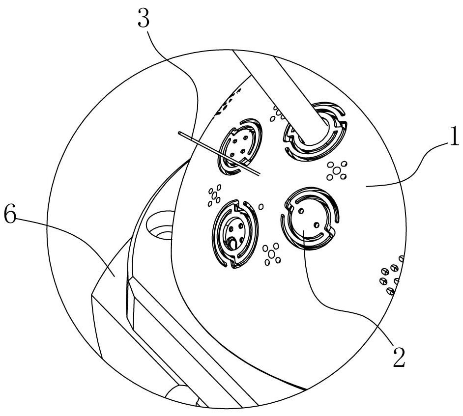
The invention relates to a laser cutting machine for a workpiece hole site . The laser cutting machine comprises a machine frame and a laser cutting machine head assembled above the machine frame, a positioning jig, a rotary workbench and a camera device are assembled on the machine frame, the positioning jig is rotatably assembled on the rotary workbench and provided with a first channel, the rotary workbench is provided with a second channel, the camera device obtains image data of the lower surface of the to-be-cut workpiece assembled on the positioning jig through the second channel and the first channel in sequence, a control device outputs a rotation control signal according to the image data, the rotary workbench controls the positioning jig to rotate by a certain angle according to the rotation angle information so as to adjust the to-be-cut position of the to-be-cut workpiece, and the control device is in communication connection with the camera device, the rotary workbench and the laser cutting machine head. According to the invention, the software and hardware cost of the machine is reduced, and the processing efficiency and reliability are improved.

Description

technical field [0001] The invention relates to the technical field of laser cutting, in particular to a laser cutting machine for workpiece holes. Background technique [0002] The CCD laser cutting machine in the traditional technology uses a CCD camera to be set directly above the workpiece to be cut to collect images of the front of the workpiece to be cut, and then link the laser cutting head to realize laser cutting. Adjust the position of the workpiece to be cut or adjust the position of the laser cutting head through the manipulator to achieve laser cutting at different angles. This type of machine requires a control device that needs to regulate and process more data, so the data processing of many control systems High precision and mechanical control precision are required, so the manufacturing cost is relatively high, and the structure of the machine is relatively complicated, occupying a large space, and the maintenance cost is often high. [0003] The Chinese u...

Claims


Application Information

Patent Timeline
IPC IPC(8): B23K26/38B23K26/70
CPCB23K26/38B23K26/702
Inventor 刘文
Owner GBOS LASER INC
Why Eureka
Try Eureka