
Interphase short circuit fault processing method

A fault handling method and phase-to-phase short-circuit technology, applied in emergency protection circuit devices, electrical components, etc., can solve problems such as large power grid impact, line damage, and long time to deal with faults.

Pending Publication Date: 2021-11-30
BAODING YUXIN ELECTRICAL TECH
View PDF9 Cites 16 Cited by
  • Summary
  • Abstract
  • Description
  • Claims
  • Application Information

AI Technical Summary

Problems solved by technology

2. Adopt the time-level difference coordination method: that is, the same line circuit breaker sets different over-current tripping times according to the distance from the power supply. The closer the distance to the power supply, the longer the tripping time. Generally, the setting level difference is 100ms. This time is determined by the mechanical switch. The action duration is determined by the time spent on the algorithm. This method can isolate the fault area. However, for faults where the fault point is close to the power supply, the power supply system can withstand short-circuit current for a long time and have a large impact on the power grid.
However, during this operation, the uncut circuit breaker and the power supply system are continuously subjected to a large short-circuit current impact. If the time is too long or the number of times is too high, the circuit will be damaged.
If the duration of the phase-to-phase short circuit cannot exceed 300 milliseconds, and the circuit breaker trip time is 100 milliseconds, then generally there should not be more than three circuit breakers on the line, otherwise the above method may cause the line to exceed 300 milliseconds.
It can be seen that the existing interphase short circuit processing methods all have the disadvantages of taking a long time to deal with the fault and not being able to automatically eliminate the fault

Method used


Image

  • Interphase short circuit fault processing method

Examples


Embodiment Construction

[0017] Below in conjunction with accompanying drawing, the present invention will be further described by specific embodiment:

[0018] The three-phase power supply system is a common non-effective grounding system. Generally, there are multiple outgoing lines on the busbar of the three-phase power supply system, and multiple controlled switches are set on each outgoing line. The controlled switches can detect one-phase, two-phase The current duration of one phase or three phases can be set, and the three-phase line can be cut off when the current duration of any phase reaches the preset value. In a specific embodiment about the controlled switch, the controlled switch includes a control unit, a current detection unit and an execution unit, the current detection unit can respectively detect the current of each phase of the three-phase line, and the control unit will detect the current detected by the current detection unit The duration is compared with the preset value, and it...


PUM


Abstract

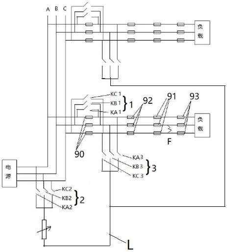
The invention discloses an inter-phase short circuit fault processing method, and the method comprises the following steps: when a two-phase or three-phase inter-phase short circuit occurs in a line, maintaining one fault phase of the line to be conducted, tripping off other fault phases, and connecting another fault phase conducted with the fault phase with a public lead; enabling the three-phase non-effective grounding power supply system to be connected with the common lead, enabling a live-line phase or a neutral point of the three-phase non-effective grounding power supply system except the fault phase to be connected with the common lead so as to form a closed loop with the fault phase and generate current, detecting current duration through controlled switches, and when a certain controlled switch reaches a triggering condition and cuts off a line, eliminating the fault. According to the method, the inter-phase short-circuit fault point interval can be quickly positioned, the fault can be automatically, quickly and accurately removed, the processing quality of the inter-phase short-circuit fault can be well improved, and the power supply safety is improved.

Description

technical field [0001] The invention relates to the field of fault processing of power supply systems, in particular to a processing method for phase-to-phase short-circuit faults in a three-phase non-effectively grounded power supply system. Background technique [0002] At present, when a phase-to-phase short circuit occurs in a line of a three-phase non-effectively grounded power supply system, the usual method is: 1. Use the reclosing method: first cut off the first circuit breaker on the line and then close the first breaker If it is an instantaneous phase-to-phase short circuit and it is eliminated after closing the first circuit breaker, the normal power supply will continue. If the phase-to-phase short-circuit fault still exists after closing the first circuit breaker, cut off the first circuit breaker and wait for maintenance. 2. Adopt the time-level difference coordination method: that is, the same line circuit breaker sets different over-current tripping times ac...

Claims


Application Information

Patent Timeline
IPC IPC(8): H02H7/26H02H7/28H02H7/22
CPCH02H7/26H02H7/28H02H7/22
Inventor 薛占钰丁同同刘建伟
Owner BAODING YUXIN ELECTRICAL TECH
Learn More