Acoustic propagation system

A sound propagation, plane technology, applied in the field of sound propagation, can solve the problems of reduced sound quality, energy loss, large structure occupied size, etc., to achieve the effect of improving sound quality

Inactive Publication Date: 2021-11-30
苏州星航综测科技有限公司 +1
View PDF0 Cites 1 Cited by
  • Summary
  • Abstract
  • Description
  • Claims
  • Application Information

AI Technical Summary

Problems solved by technology

In terms of structure, its coil and paper cone are designed as independent structures, and its structure occupies a large size. After the size and material are fixed, the adjustable range of the coil is fixed, and the frequency of the sound vibration formed by it will be limited within a fixed range. Moreover, the vibration transmission process will produce energy loss, resulting in reduced sound quality

Method used


Image

  • Acoustic propagation system
  • Acoustic propagation system
  • Acoustic propagation system

Examples


Embodiment Construction

[0027] The present invention will be further described below in conjunction with the accompanying drawings and specific embodiments, so that those skilled in the art can better understand the present invention and implement it, but the examples given are not intended to limit the present invention.

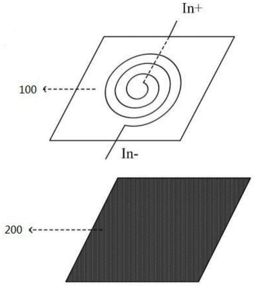
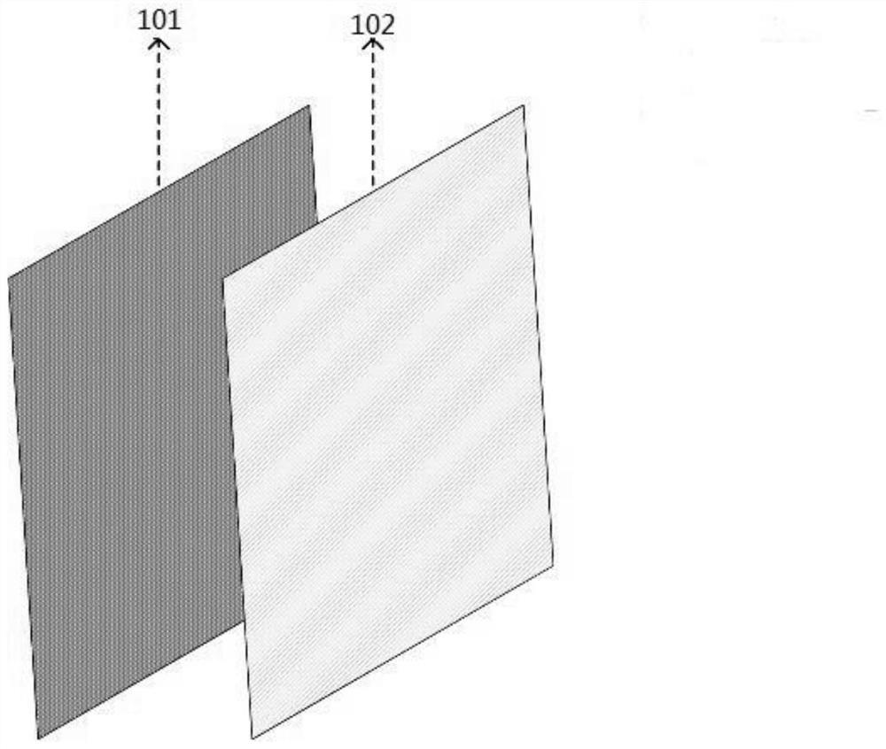
[0028] see Figure 2 to Figure 6 As shown, the present invention provides a sound propagation system, including a planar resonant circuit, the planar resonant circuit includes a planar resonator 100 and a permanent magnet 200, the planar resonator 100 includes a metal layer 110 and a flexible film substrate layer 120, and the metal layer 110 is pressed on the flexible film substrate layer 120.

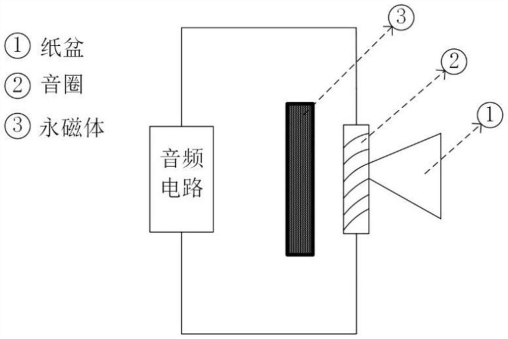
[0029] The sounding principle of the above-mentioned planar resonant circuit is: when an alternating current passes through the planar resonator 100 , different magnetic fields will be generated, which will interact with the permanent magnet 200 at the bottom to generate vibration and soun...


PUM


Abstract

The invention relates to an acoustic propagation system, which comprises a planar resonance circuit that comprises a planar resonance body and a permanent magnet, the planar resonance body comprises a metal layer and a flexible film substrate layer, and the metal layer is laminated on the flexible film substrate layer; wherein the planar resonance body comprises a plurality of planar resonance units which are distributed in an array. According to the invention, the integrated planar resonant body is designed, so that the problems that the structure occupied size is large and the sound vibration frequency is limited in a fixed range due to an independent structure in the prior art are solved. The planar resonance body comprises a plurality of planar resonance units, which are distributed in an array, so that accurate frequency control can be realized, and the sound quality is obviously improved.

Description

technical field [0001] The present invention relates to the technical field of sound propagation, in particular to a sound propagation system and a communication terminal. Background technique [0002] The traditional sound propagation process (such as the principle of acoustic vibration) is mainly the vibration of the vibrator and the sound of the paper tympanic horn. The general principle is to put the weak signal of the microphone into the front stage of the power amplifier for amplification and rendering, send it to the rear stage for amplification, and then output the signal current to the voice coil of the speaker, and then vibrate with different vibration amplitudes through the strong and weak voice coil of the current, and then vibrate the speaker paper cone to make sound. [0003] The traditional sound vibration structure includes a vibration circuit, a coil and a diaphragm (such as figure 1 As shown), the vibration circuit can be regarded as a sound source. The s...

Claims


Application Information

Patent Timeline
Patent Type & Authority Applications(China)
IPC IPC(8): H04R9/18H04R9/06H04R9/04
CPCH04R9/18H04R9/06H04R9/04
Inventor 羊箭锋周怡吴彬彬严荣慧
Owner 苏州星航综测科技有限公司
Why Eureka
Try Eureka