Material cutting machine for machining production

A technology of mechanical processing and material cutting machine, which is applied in the direction of metal processing equipment, manufacturing tools, metal sawing equipment, etc., can solve the problems of manpower consumption, non-compliance with processing specifications, and inability to ensure the smoothness of aluminum cuts, etc., to achieve improvement The effect of processing efficiency

Inactive Publication Date: 2021-12-03
ANHUI UNIVERSITY OF TECHNOLOGY AND SCIENCE
View PDF6 Cites 1 Cited by
  • Summary
  • Abstract
  • Description
  • Claims
  • Application Information

AI Technical Summary

Problems solved by technology

[0004] In the prior art, when the raw material is placed on the workbench, only the aluminum material is longitudinally squeezed and limited, resulting in an angle between the aluminum material and the saw blade. When the saw blade cuts the aluminum material, due to the angle deviation However, it cannot ensure that the incision of the aluminum material is flat, which does not meet the processing specifications, and it is labor-intensive to manually adjust the placement angle of the aluminum material; therefore, a cutting machine for mechanical processing and production is proposed to solve the above problems

Method used


Image

  • Material cutting machine for machining production
  • Material cutting machine for machining production
  • Material cutting machine for machining production

Examples


Embodiment approach

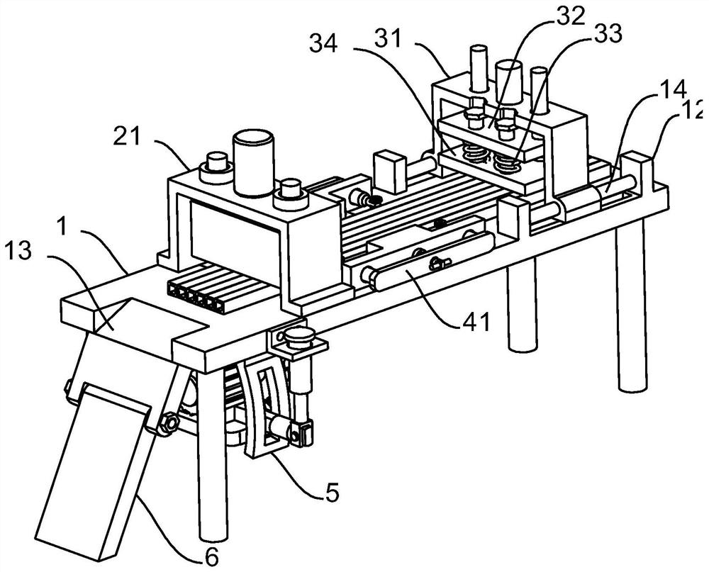
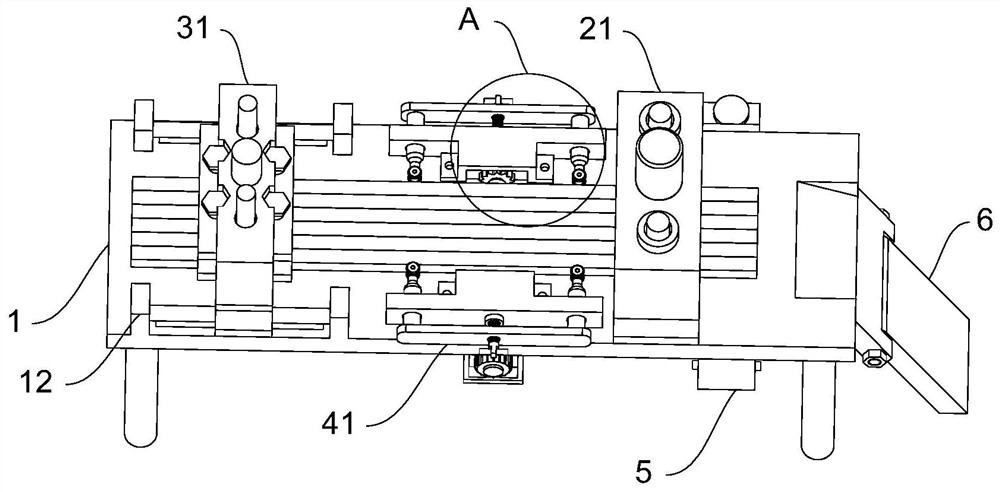
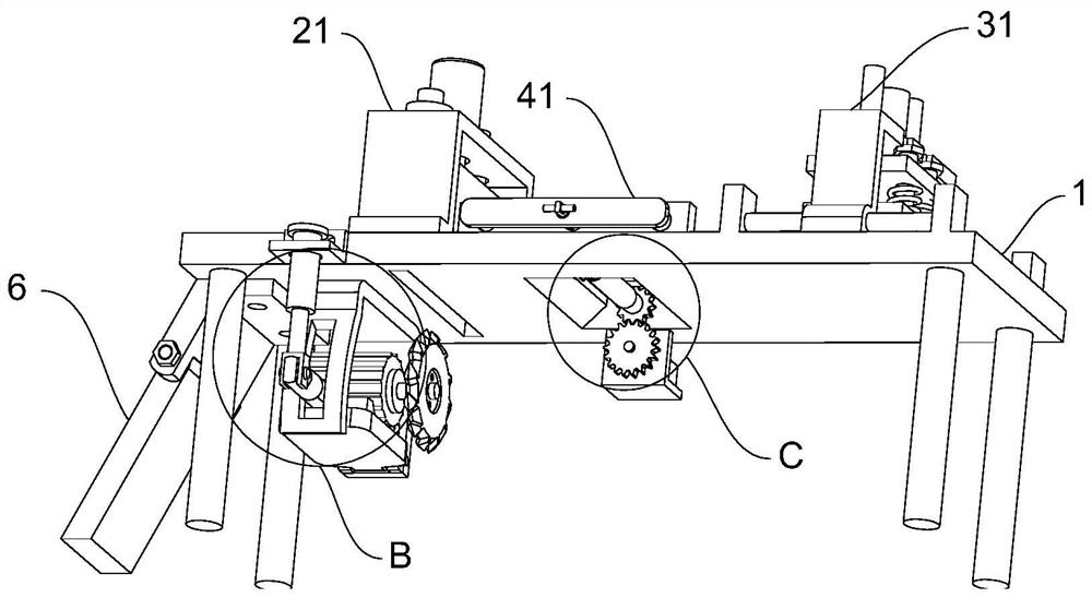
[0031] As an embodiment of the present invention, a groove 11 is provided in the middle of the bottom surface of the workbench 1, and a rotating roller 17 is rotatably connected to the inner wall of the groove 11; both ends of the rotating roller 17 are fixedly connected There is a driven gear 18, and the lower end of the driven gear 18 engages with a drive assembly 15; the drive assembly 15 is fixedly connected to one side of the workbench 1; the workbench 1 corresponds to the cutting assembly 5 One end is provided with a chute 12; the workbench 1 is provided with a through slot 16 corresponding to the No. 1 pressurizing mechanism.

[0032] During work, during the processing of aluminum materials, the driven gear 18 is driven by the No. 1 drive assembly 15 to rotate, so that the rotating roller 17 rotates, and the rotation of the rotating roller 17 will drive the aluminum material at the top of the through groove 16 to move to the cutting assembly 5 At this time, the No. 1 pr...


PUM


Abstract

The invention discloses a material cutting machine for machining production. The material cutting machine for machining production comprises a workbench; a first pressurizing mechanism and a second pressurizing mechanism are fixedly connected to the upper end of the workbench; a cutting assembly is fixedly connected to the bottom end of one side of the workbench; and adjusting assemblies are fixedly connected to the middle of the surface of the workbench. By arranging the adjusting assembly, when a long-strip-shaped aluminum material is placed on the workbench, the aluminum material is fixed through the first pressurizing mechanism and the second pressurizing mechanism, then a threaded rod is manually rotated to drive a movable plate to move, the movable plate drives a connecting column and a rotating wheel to move on the workbench, the adjusting assemblies on the two sides synchronously move, and finally clamping on the aluminum material is achieved; and as the length of the connecting column is fixed, it can be guaranteed that the aluminum material is parallel to the workbench when the aluminum material is clamped through the connecting column, and the situation that during subsequent machining, due to the fact that the aluminum material is obliquely arranged, a notch is inclined after the aluminum material is cut, and subsequent machining and selling of the aluminum material are affected is avoided.

Description

technical field [0001] The invention relates to the technical field of cutting machines, in particular to a cutting machine for machining production. Background technique [0002] The cutting machine is a device that can process long strips of metal materials, such as processing long strips of aluminum, and is widely used in major machinery processing plants. [0003] In today's mechanical processing field, the cutting machine cuts the long strip of aluminum placed on the workbench with a saw blade, and cuts it into a fixed-length aluminum workpiece, thereby completing the processing of a certain length of aluminum. [0004] In the prior art, when the raw material is placed on the workbench, only the aluminum material is longitudinally squeezed and limited, resulting in an angle between the aluminum material and the saw blade. When the saw blade cuts the aluminum material, due to the angle deviation However, it cannot ensure that the cut of the aluminum material is smooth, ...

Claims


Application Information

Patent Timeline
Patent Type & Authority Applications(China)
IPC IPC(8): B23D45/06B23D47/04
CPCB23D45/06B23D47/045
Inventor 李传瑞王静平张春霞李月英乔振亮汪天赐
Owner ANHUI UNIVERSITY OF TECHNOLOGY AND SCIENCE
Why Eureka
Try Eureka