Supercharge Your Innovation With Domain-Expert AI Agents!

Manipulator for continuously grabbing test pieces

A technology for grasping manipulators and test pieces, applied in the field of test pieces, it can solve the problems of inability to control the initial position and end position, and inability to transfer test pieces, and achieve the effect of increasing efficiency, quick connection and rich functions.

Active Publication Date: 2021-12-03
深圳市福瑞达电子有限公司
View PDF5 Cites 0 Cited by
  • Summary
  • Abstract
  • Description
  • Claims
  • Application Information

AI Technical Summary

Problems solved by technology

[0003] In the prior art, the frame-shaped test piece can be quickly installed and disassembled, and at the same time, the frame-shaped test piece can be locked and limited to prevent the frame-shaped test piece from moving. The overall structure is easy to replace and disassemble through the installation shaft, but the existing technology cannot It serves the purpose of transferring the test piece, and at the same time, it cannot control the transfer stroke and the initial position and end position of the stroke, so the existing technology has a large room for improvement

Method used


Image

  • Manipulator for continuously grabbing test pieces
  • Manipulator for continuously grabbing test pieces
  • Manipulator for continuously grabbing test pieces

Examples


Embodiment 1

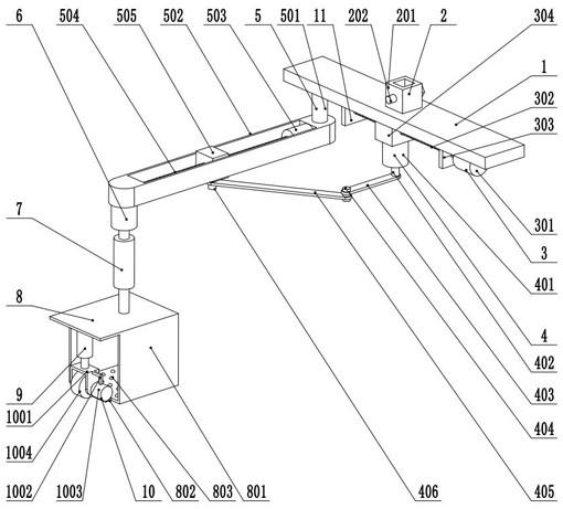
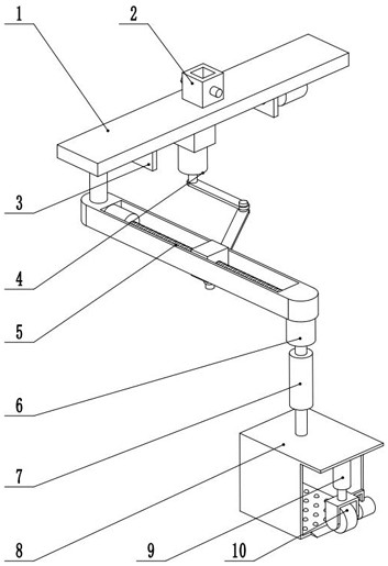
[0028] see Figure 1-3 , a manipulator for continuous grabbing of test pieces, including a mount 1,

[0029] The mounting seat 1 is fixedly connected to the connecting mechanism 2;

[0030] The mounting seat 1 is fixedly connected to the transposition assembly 11, and the transposition assembly 11 includes a displacement mechanism 3, a link mechanism 4 and a transposition lever mechanism 5, and the displacement mechanism 3 and the transposition lever mechanism 5 are all located on the mounting seat 1, and are connected to each other. The rod mechanism 4 is arranged between the displacement mechanism 3 and the shift rod mechanism 5, the displacement mechanism 3 is used to adjust the position of the link mechanism 4, and the link mechanism 4 is used to drive the shift rod mechanism 5 to swing;

[0031] The transposition lever mechanism 5 is fixedly connected to the first motor 6;

[0032] The output shaft of the first motor 6 is fixedly connected to the electric push rod 7;

...

Embodiment 2

[0047] see Figure 1-3 , the other content of this embodiment is the same as that of Embodiment 1, except that the pressing mechanism 9 includes a pressing sleeve 901 fixed on the box body 801, and a spring 902 is fixedly connected in the pressing sleeve 901, and the spring The end of 902 away from the compression sleeve 901 is fixedly connected to the compression block 903, the compression block 903 and the compression sleeve 901 are slidingly connected, and the side of the compression block 903 away from the spring 902 is fixedly connected to the compression rod 904, and the compression rod 904 Pass through the compression sleeve 901 and be slidably connected with the compression sleeve 901 .

[0048] In the implementation process of the present invention, the integral manipulator is first connected with other parts through the connecting mechanism 2, and then when the grasping stroke needs to be adjusted, the displacement mechanism 3 is opened at this time, thereby realizing ...


PUM


Abstract

The invention discloses a manipulator for continuously grabbing test pieces, and relates to the field of test pieces. The manipulator comprises a mounting seat, and the mounting seat is fixedly connected with a connecting mechanism; the mounting seat is fixedly connected with a transposition assembly, and the transposition assembly comprises a displacement mechanism, a connecting rod mechanism and a transposition rod mechanism; the transposition rod mechanism is fixedly connected with a first motor; an output shaft of the first motor is fixedly connected with an electric push rod; the electric push rod is fixedly connected with a box grabbing mechanism; the box grabbing mechanism is fixedly connected with a pressing mechanism; and the pressing mechanism is fixedly connected with a grabbing wheel mechanism. According to the manipulator, the whole device can be quickly connected with other parts by arranging the connecting mechanism, the transposition rod mechanism can be driven to swing by arranging the connecting rod mechanism, the test pieces can be transferred, the swing stroke can be adjusted by combining the displacement mechanism and the transposition rod mechanism, it can be guaranteed that the grabbing wheel mechanism is attached to the test pieces for grabbing by arranging the pressing mechanism, and therefore the grabbing and moving efficiency of the test pieces is improved, and meanwhile, the functions of the whole device are enriched.

Description

technical field [0001] The invention relates to the field of test pieces, in particular to a manipulator for continuously grabbing test pieces. Background technique [0002] The test piece refers to the silicon wafer used for processing technology inspection, area and processing cleanliness inspection. The grade is higher than the mechanical test piece and lower than the positive film. [0003] In the prior art, the frame-shaped test piece can be quickly installed and disassembled, and at the same time, the frame-shaped test piece can be locked and limited to prevent the frame-shaped test piece from moving. The overall structure is easy to replace and disassemble through the installation shaft, but the existing technology cannot The purpose of transferring the test piece is achieved, and at the same time, the transfer stroke, the initial position and the end position of the stroke cannot be controlled, so there is a large room for improvement in the prior art. Contents of...

Claims


Application Information

Patent Timeline
Patent Type & Authority Applications(China)
IPC IPC(8): B25J9/00B25J9/10B25J9/12B25J15/00
CPCB25J9/0009B25J9/10B25J9/126B25J15/0019
Inventor 黄丽匡娟
Owner 深圳市福瑞达电子有限公司
Features
  • R&D
  • Intellectual Property
  • Life Sciences
  • Materials
  • Tech Scout
  • Unparalleled Data Quality
  • Higher Quality Content
  • 60% Fewer Hallucinations
Learn More