Manipulator for precise injection molding and operation method thereof

An injection molding and manipulator technology, applied in the field of manipulators, can solve the problems of no auxiliary structure, affecting workpiece processing, workpiece shaking, etc., and achieves the effects of high stability, improved applicability, and prevention of workpiece falling.

Pending Publication Date: 2021-12-03
河北敬业增材制造科技有限公司
View PDF0 Cites 0 Cited by
  • Summary
  • Abstract
  • Description
  • Claims
  • Application Information

AI Technical Summary

Problems solved by technology

[0004] At present, when the injection molded workpiece is processed, the manipulator is generally used to grab the workpiece, but when the existing manipulator grips the workpiece, because the gripper adopts the method of grabbing the workpiece, this kind of gripping In this way, the workpiece will be deformed, which will damage the workpiece, and there is no auxiliary structure. After grabbing, the workpiece will often shake, which will cause sliding friction between the jaws and the workpiece, resulting in damage to the surface of the workpiece. At the same time, the general splint The style is single, but the shape of the workpiece is different, which makes it impossible for the manipulator to be unified with the shape of the workpiece, and then cannot be clamped, which affects the processing of the workpiece

Method used


Image

  • Manipulator for precise injection molding and operation method thereof
  • Manipulator for precise injection molding and operation method thereof
  • Manipulator for precise injection molding and operation method thereof

Examples


Embodiment approach

[0037] In order to better demonstrate the implementation process of the manipulator for precision injection molding, this embodiment now proposes an implementation method of the manipulator for precision injection molding, including the following steps:

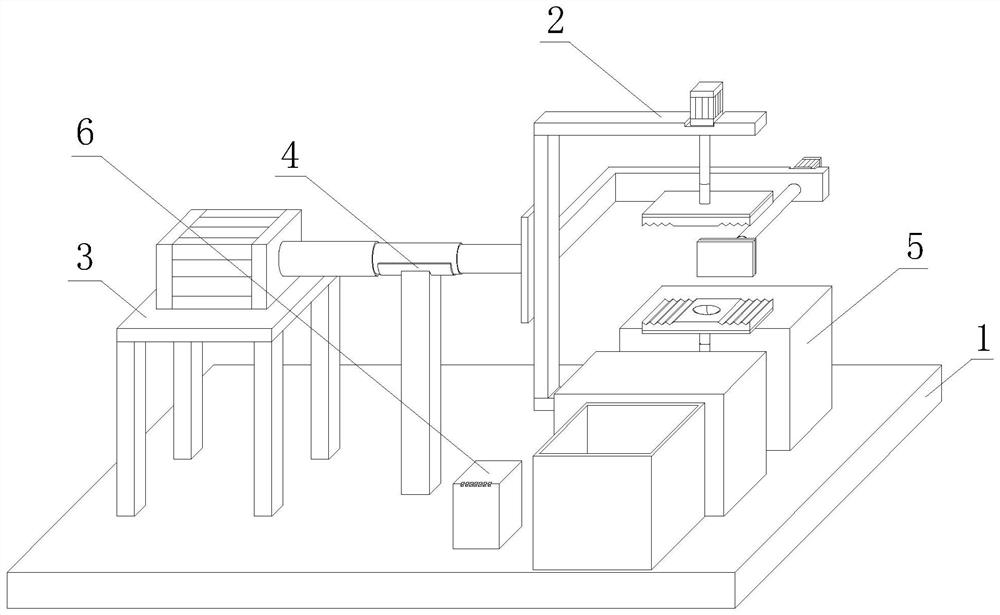
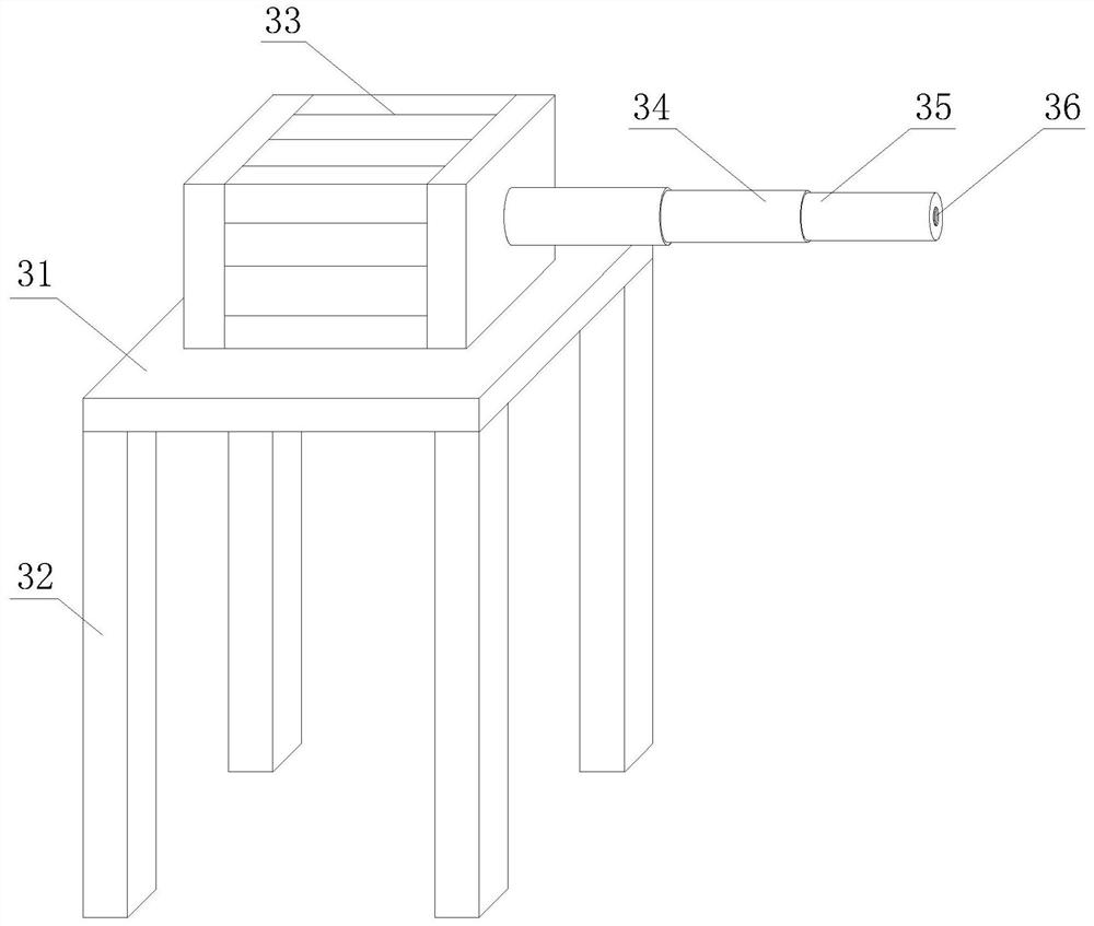
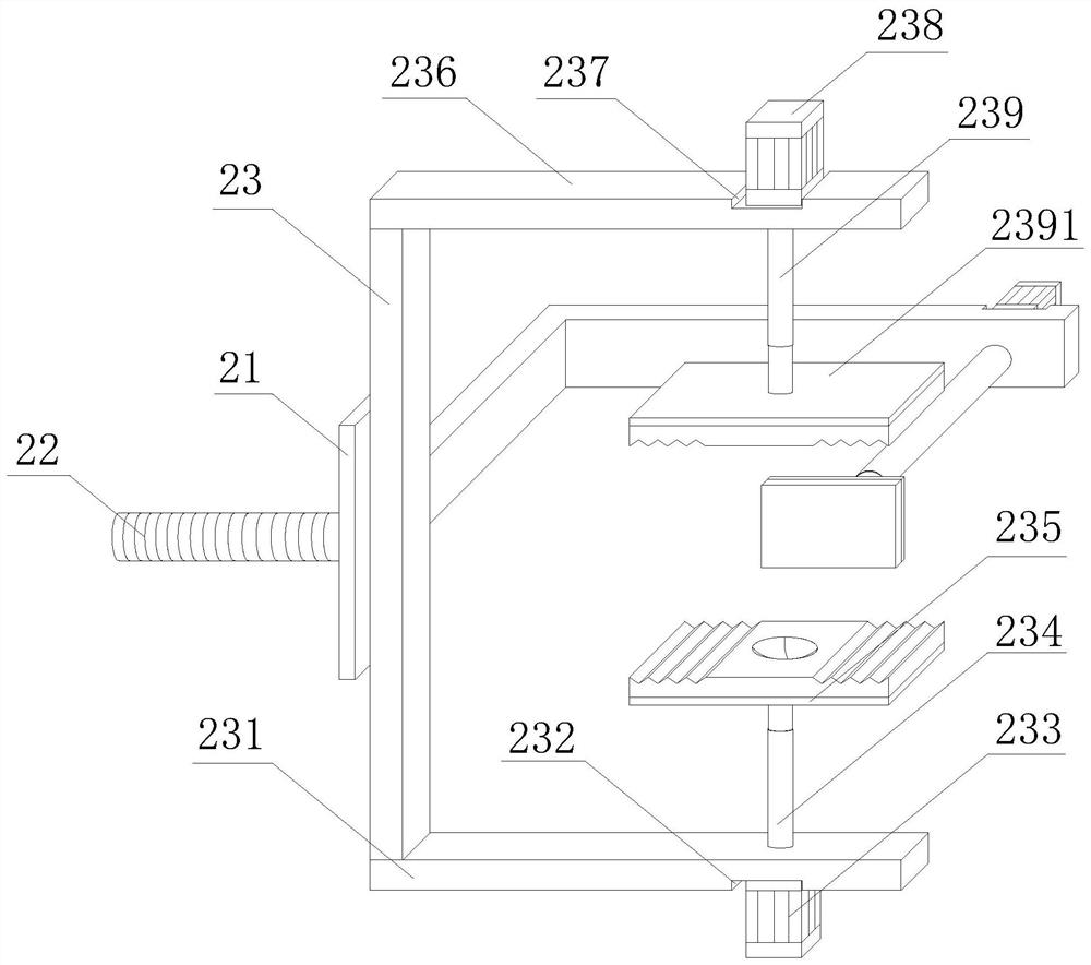
[0038] Step 1: The PLC controller 6 controls the start of the fourth hydraulic pump 33, the fourth hydraulic pump 33 drives the fourth hydraulic telescopic column 34 to expand and contract to the right, and the fourth hydraulic telescopic column 34 drives the grasping assembly 2 to move to the right until the lower The grabbing plate 235 enters the inside of the limit channel 52, so that the lower grabbing plate 235 is flush with the precision injection molded workpiece placed on the upper grabbing plate 2391 and the storage table 51. When the PLC controller 6 controls the fourth hydraulic pump 33 to stop operating ;

[0039] Step 2: Then the PLC controller 6 controls the first hydraulic pump 233 to start, the first hydraulic...


PUM


Abstract

The invention discloses a manipulator for precise injection molding and an operation method thereof. According to the manipulator for precise injection molding and the operation method thereof, a threaded column is arranged on the side face of a stabilizing plate, a connecting plate is arranged on the other side face of the stabilizing plate, a lower fixing plate is arranged at the bottom of the connecting plate, a first limiting groove is formed in the bottom of the lower fixing plate, a first hydraulic pump is arranged in the first limiting groove, a first hydraulic telescopic column is arranged at the position, corresponding to the first hydraulic pump, of the top of the lower fixing plate, the bottom end of the first hydraulic telescopic column penetrates through the lower fixing plate to be connected with the first hydraulic pump, a lower grabbing plate is arranged at the top end of the first hydraulic telescopic column, a second limiting groove is formed in the position, corresponding to the first limiting groove, of the top of an upper fixing plate, a second hydraulic pump is arranged in the second limiting groove, and a second hydraulic telescopic column is arranged at the position, corresponding to the second hydraulic pump, of the bottom of the upper fixing plate. The manipulator for precise injection molding and the operation method thereof have the advantages that buffering is achieved during grabbing, workpieces are protected against deformation, the stability is high, the workpieces are prevented from falling off, and the applicability is greatly improved.

Description

technical field [0001] The invention relates to the technical field of manipulators, in particular to a manipulator for precision injection molding and an operating method thereof. Background technique [0002] Beer (pi) machine, injection molding machine (referred to as injection machine or injection molding machine) is the main molding equipment for making thermoplastic or thermosetting materials into various shapes of plastic products with plastic molding molds. The word beer has only one pronunciation (pi), However, in the field of printing, the word "beer" is often mispronounced as bie, which is influenced by Cantonese, because injection molding developed relatively early in Guangdong and Hong Kong, and the injection system is one of the most important components of the injection molding machine, usually with a plunger There are three main forms: screw type, screw type, and screw pre-molded plunger injection type. The most widely used is the screw type. Its function is ...

Claims


Application Information

Patent Timeline
Patent Type & Authority Applications(China)
IPC IPC(8): B29C45/42B25J15/00
CPCB29C45/4225B25J15/0033B29C2045/4241B29C2045/4283
Inventor 张觉灵杨海西刘博张帅姚淑英
Owner 河北敬业增材制造科技有限公司
Why Eureka
Try Eureka