
Sealing device of tensioning structure

A technology of sealing device and tensioning plate, which is applied in the direction of distribution device, special distribution device, liquid distribution, conveying or transfer device, etc. It can solve the problems of non-self-locking, high manufacturing cost, inconvenient installation, etc., and achieve reliable sealing and structure Simple, easy-to-install effect

Pending Publication Date: 2021-12-03
新疆先达智控科技有限公司
View PDF8 Cites 0 Cited by
  • Summary
  • Abstract
  • Description
  • Claims
  • Application Information

AI Technical Summary

Problems solved by technology

The above-mentioned invention adopts a four-bar linkage structure, which has many hinge points and is inconvenient to install, and both the four-bar linkage mechanism and the inclined cone are centered on the oil injection pipe. When using cylinder power, it cannot be self-locked. When using oil cylinder, hydraulic oil leakage will easily pollute the loading oil. The structure of the entire sealing device is complicated and the manufacturing cost is high.

Method used

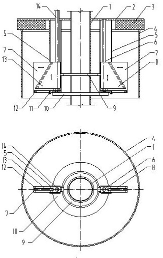

Image

  • Sealing device of tensioning structure
  • Sealing device of tensioning structure

Examples


Embodiment Construction

[0024] The specific implementation manner of the present invention will be described in detail below in conjunction with the accompanying drawings.

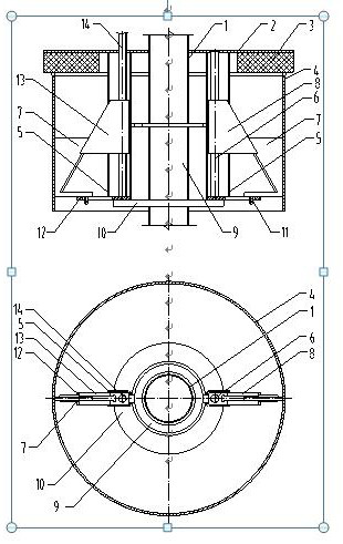
[0025] refer to figure 1 , figure 2 as shown, figure 1 , figure 2 Schematic diagram of the structure of the novel tension structure sealing device provided by the present invention. The novel tensioning structure sealing device provided by the present invention includes: an oil injection pipe 1, a sealing cover 2, a sealing gasket 3, a tank mouth 4, a rectangular guide pipe 5, a guide rod 6, a tensioning plate 7, a trapezoidal slider 8, Connecting ring 9, fixed ring 10, limit pin 11, supporting plate 12, trapezoidal nut 13, screw rod 14.

[0026] Wherein, the sealing cover 2 is arranged on the upper end surface of the tank mouth 4 of the fuel tanker, and the sealing gasket 3 is arranged at the lower end of the seal cover 2, and is the same in diameter as the seal cover 2, and is used for sealing the tank mouth 4 of the fuel...


PUM


Abstract

The invention provides a sealing device of a tensioning structure. The sealing device comprises an oil injection pipe, a sealing cover, a sealing gasket, a tank car tank opening, rectangular guide pipes, guide rods, a tensioning plate, trapezoidal sliding blocks, connecting rings, a fixing ring, limiting pins, a supporting plate, trapezoidal nuts and screw rods, wherein the sealing device of the tensioning structure is arranged in the tank car tank opening; one end of the tensioning plate is embedded into trapezoidal nut and trapezoidal sliding block conical surface grooves, the screw rods drive the trapezoidal nuts to move up and down in the rectangular guide pipes, the trapezoidal nuts are connected with the trapezoidal sliding blocks through the connecting rings, and the connecting rings drive the trapezoidal sliding blocks to move up and down in the rectangular guide pipes with the guide rods as the axes; and when the trapezoidal nuts and the trapezoidal sliding blocks move upwards, the tensioning plate is pushed out by the trapezoidal nuts and the trapezoidal sliding blocks to horizontally move outwards so as to be tensioned with the inner wall of the tank car tank opening, the limiting pins are fixed to the tensioning plate and move in supporting plate grooves, one end of each limiting pin is hung on the bottom of the supporting plate, and the tensioning failure caused by upward movement of the tensioning plate due to the acting force of the tensioning plate and the tank car tank opening when the trapezoidal nuts and the trapezoidal sliding blocks move upwards is prevented. The upper ends of the rectangular guide pipes, the guide rods and the screw rods of the sealing device of the tensioning structure are fixed to the sealing cover, and the lower ends are connected with the supporting plate and the fixing ring. The sealing device of the tensioning structure is simple in overall structure, low in manufacturing cost, convenient to install, reliable in sealing, safe, environmentally friendly and capable of adapting to tank car tank openings with different hole diameters.

Description

technical field [0001] The invention relates to a sealing device for a tank mouth of a tank truck, in particular to a novel sealing device with a tensioning structure. Background technique [0002] In the petrochemical industry, during the loading process of fluids, most of them adopt airtight loading, that is, the sealing cover is covered on the tank mouth of the tanker, and the oil injection pipe is directly inserted into the tank mouth of the tanker. The generated oil and gas back pressure will lift the sealing cover, causing the oil and gas generated during the loading process to be directly discharged into the atmosphere, polluting the environment and causing safety accidents, and also causing oil and gas recovery failure and oil and gas waste. [0003] Chinese invention patent 201610276525.7: An inner support type sealing device discloses a pneumatic inner support type sealing device, which is installed on the vertical pipe of the top-mounted crane pipe, and is charact...

Claims


Application Information

Patent Timeline
Patent Type & Authority Applications(China)
IPC IPC(8): B67D7/02B67D7/04B67D7/54B67D7/78
CPCB67D7/02B67D7/04B67D7/54B67D7/78
Inventor 李建新
Owner 新疆先达智控科技有限公司
Learn More