Combined partition plate in building and construction method thereof
A construction method and technology in the building, applied in the direction of building, building components, building structure, etc., can solve the problem that the decorative board does not have the dustproof function, and affects the normal movement of the telescopic frame in the decorative board.
- Summary
- Abstract
- Description
- Claims
- Application Information
AI Technical Summary
Problems solved by technology
Method used
Image
Examples
Embodiment 1
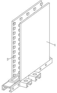
[0048] see Figure 1-3 , in an embodiment of the present invention, a composite partition in a building, comprising
[0049] Decorative board 1, the inner surface of the decorative board 1 is vertically arranged in an up-and-down vertical direction, and there are several dust-proof components 2 that can be collected in time when dust falls into the decorative board 1 to prevent dust from accumulating in the decorative board 1;
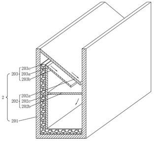
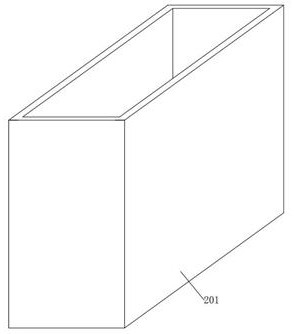
[0050] The dustproof assembly 2, the dustproof assembly 2 includes a dustproof case 201, a dust guide assembly 202 that can guide dust collection, and a dust suction assembly 203 that can absorb dust;
[0051] The outer surface of a longitudinal side of the dustproof case 201 is fixedly arranged on the inner surface of the decorative panel 1 in an up-and-down vertical direction;
[0052] A dust guide assembly 202 is movably installed between the top and the middle end of the dustproof case 201;
[0053] A dust suction assembly 203 is movably installe...
Embodiment 2
[0058] see figure 2 , Figure 4 and Figure 6 Compared with Embodiment 1, this embodiment of the present invention differs in that: the dust guide assembly 202 includes:
[0059] On the upper guide plate 202a, the top position of the left inner wall of the dustproof case 201 is obliquely fixedly installed with the upper guide plate 202a, the angle between the upper guide plate 202a and the horizontal plane is 40°, and the right end tail of the upper guide plate 202a is stored before the right inner wall of the dustproof case 201. There are intervals;
[0060] Here, the angle between the upper guide plate 202a and the horizontal plane is set at 40° to ensure that the dust falling through the gap at the top of the dustproof case 201 can slide down to the right along the outer surface of the top side of the upper guide plate 202a without accumulation. On the top side surface of the upper guide plate 202a, the dust that slides down along the upper guide plate 202a can fall dow...
Embodiment 3
[0069] see figure 2 , Figure 5-6 Compared with Embodiment 1, this embodiment of the present invention differs in that: the dust suction assembly 203 includes:
[0070] The limiting plate 203a, the position between the upper left end of the dustproof case 201a and the lower part is fixedly installed in the vertical direction. The limiting plate 203a is fixedly installed on the front and rear inner walls of the dustproof case 201 respectively At the left end position, there is an interval between the top and bottom ends of the limiting plate 203a to the bottom outer surface of the upper guide plate 202a and the bottom inner wall of the dustproof case 201, and the material of the limiting plate 203a is also iron. The right outer surface is magnetically attached to the left outer surface of the rotating plate 202c under normal circumstances. The top of the limiting plate 203a has a slope that is high on the left and low on the right, and the angle between the slope and the hori...
PUM
 Abstract
Description
Claims
Application Information
 - R&D
- Intellectual Property
- Life Sciences
- Materials
- Tech Scout
- Unparalleled Data Quality
- Higher Quality Content
- 60% Fewer Hallucinations
Browse by: Latest US Patents, China's latest patents, Technical Efficacy Thesaurus, Application Domain, Technology Topic, Popular Technical Reports.
© 2025 PatSnap. All rights reserved.Legal|Privacy policy|Modern Slavery Act Transparency Statement|Sitemap|About US| Contact US: help@patsnap.com


