Supercharge Your Innovation With Domain-Expert AI Agents!

Liquefied gas pipeline connector protection device and method

A technology for pipeline joints and protective devices, which is applied to pipeline systems, pipes/pipe joints/fittings, pipe components, etc. It can solve problems such as early warning, natural gas pipeline blockage, and small gas leakage, and achieve the effect of avoiding continuous leakage

Pending Publication Date: 2021-12-03
芜湖中燃城市燃气发展有限公司
View PDF19 Cites 3 Cited by
  • Summary
  • Abstract
  • Description
  • Claims
  • Application Information

AI Technical Summary

Problems solved by technology

[0004] However, there are still some defects in the use of this device. Due to the small amount of gas leakage in the initial stage of liquefied gas leakage, it is often difficult to find it. Pipelines are blocked to prevent continuous leakage of natural gas. Based on the above problems, we provide a protective device and method for liquefied gas pipeline joints

Method used


Image

  • Liquefied gas pipeline connector protection device and method
  • Liquefied gas pipeline connector protection device and method
  • Liquefied gas pipeline connector protection device and method

Examples


Embodiment 1

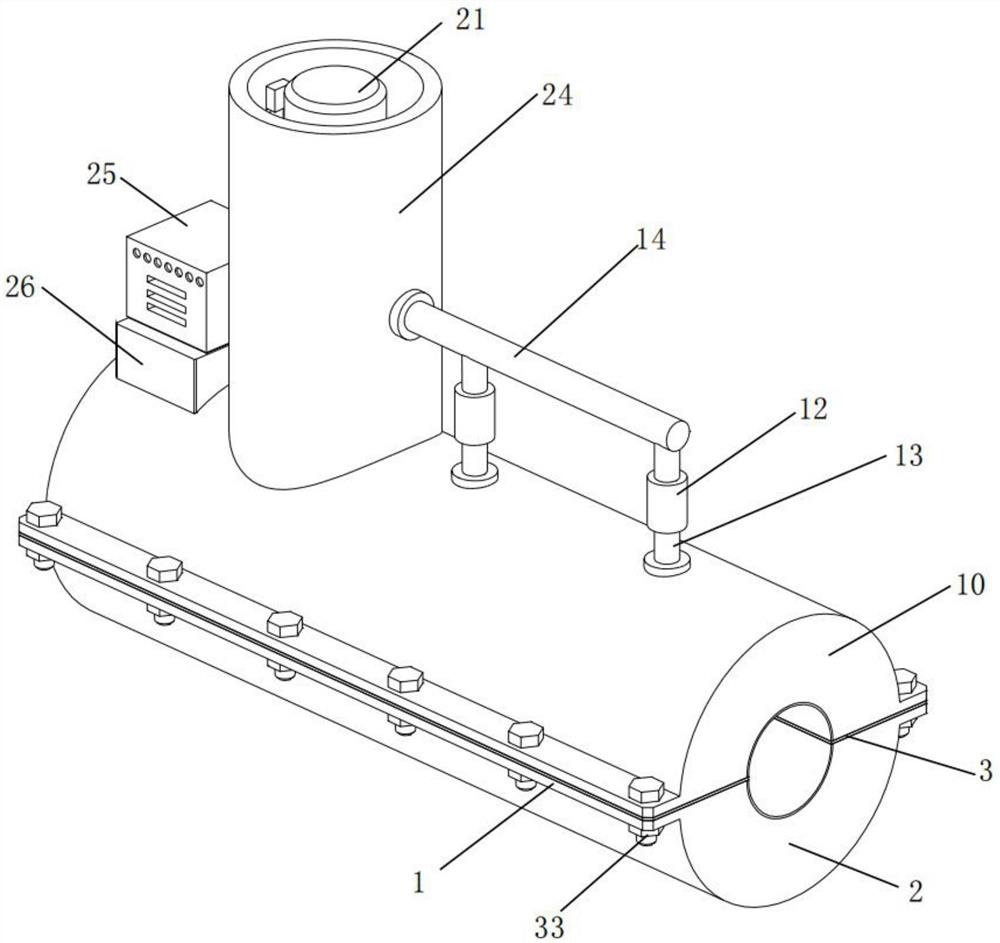
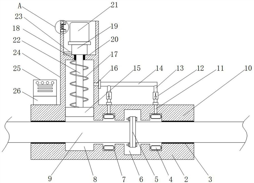
[0030] see Figure 1-Figure 5 , in an embodiment of the present invention, a liquefied gas pipeline interface protection device includes an upper protection block 10 and a lower protection block 2, both sides of the upper protection block 10 and the lower protection block 2 are provided with connecting side plates 1, the The upper protection block 10 and the lower protection block 2 are fixedly connected by locking and connecting the side plate 1 with the locking bolt 33, and the inside of the upper protection block 10 and the lower protection block 2 is located at the interface 5 of the liquefied gas pipeline 9 to open a receiving groove 6, so The upper protection block 10 and the lower protection block 2 are provided with sealing grooves 7 at both sides of the accommodation groove 6, and the sealing grooves 7 are provided with a secondary sealing assembly for forming a seal; the upper protection block 10 and the Sealing gaskets 3 made of rubber are pasted on opposite sides a...

Embodiment 2

[0039] see Image 6 The difference from Embodiment 1 is that the upper end of the installation cylinder 24 is rotatably connected with a circular cover 34 made of plastic material; the circular cover provided can prevent dust from accumulating in the installation cylinder 24 when the device is used in the open air or rain.

[0040] The working principle of the present invention is: when the present invention is in use, two annular airbags 4 are sleeved to the positions on both sides of the interface 5 first, and the annular airbags 4 are aligned with the sealing groove 7, and then the upper protection block 10 and the lower protection block The block 2 is installed at the interface 5 of the liquefied gas pipeline 9, and locked with a locking bolt 33, connecting the side plate 1 and the opposite side of the sealing gasket 3 and the sealing gasket 3 provided on the arc surface can ensure that the upper protection block 10 and the lower The tightness of the protection block 2, w...


PUM


Abstract

The invention discloses a liquefied gas pipeline connector protection device and method. The device comprises an upper protection block and a lower protection block, wherein connecting side plates are arranged on the two sides of the upper protection block and the two sides of the lower protection block correspondingly, the upper protection block and the lower protection block are fixedly connected by locking the connecting side plates through locking bolts, containing grooves are formed in the upper protection block and the lower protection block and located at the joint of a liquefied gas pipeline. When leakage occurs at the joint of the liquefied gas pipeline, air pressure in a cavity formed by the upper protection block and the lower protection block rises, a piston block, a piston rod and a limiting top block are pushed to overcome a first spring to move upwards, when the piston rod moves upwards, an alarm lamp is pushed to extend out of a mounting cylinder, when the limiting top block moves upwards, a trigger top plate is driven to move upwards together, the trigger top plate moves upwards to push a second elastic copper block to move upwards to be in contact with a first elastic copper block, so that a circuit is switched on, the alarm lamp and a buzzer work to give an alarm at the moment, and then a worker can be reminded to go to process.

Description

technical field [0001] The invention relates to the technical field of liquefied gas transportation, in particular to a protective device and method for a liquefied gas pipeline interface. Background technique [0002] Liquefied gas Liquefied petroleum gas is a colorless volatile liquid obtained by liquefying natural gas or petroleum under pressure and cooling in an oil refinery. In the laying of liquefied gas pipelines, it is necessary to butt the pipelines by using joints or welding, but the pipeline joints are relatively weak. After the pipelines are put into use, due to the impact and vibration, the joints of the pipelines are easy to crack and leak , so the interface of the pipeline needs to be protected. [0003] The existing patent CN201720802736.X proposes a protective device at the interface of chemical pipelines. The protective device at the interface of chemical pipelines, through the first shell and the second shell arranged on the first pipeline body and the se...

Claims


Application Information

Patent Timeline
IPC IPC(8): F17D5/02F16L55/172
CPCF17D5/02F16L55/172Y02T10/30
Inventor 曹敏俊
Owner 芜湖中燃城市燃气发展有限公司
Features
  • R&D
  • Intellectual Property
  • Life Sciences
  • Materials
  • Tech Scout
  • Unparalleled Data Quality
  • Higher Quality Content
  • 60% Fewer Hallucinations
Learn More