Automatic test device forflame retardant property of firefighter protective boot and use method

A technology of flame retardancy and automatic testing, which is applied in the direction of using combustion for chemical analysis, etc. It can solve the problem that the angle and distance between the flame and the burning point are difficult to meet the specified requirements, the quality and efficiency of the test and detection are not high, and the environment where the inspectors live is harsh To achieve the effect of improving test quality and detection efficiency, eliminating human interference factors, and solving distance instability

Pending Publication Date: 2021-12-03
SHANDONG INST FOR PROD QUALITY INSPECTION
View PDF5 Cites 0 Cited by
  • Summary
  • Abstract
  • Description
  • Claims
  • Application Information

AI Technical Summary

Problems solved by technology

Because the hand-held Bunsen burner is operated by hand, it is easy to cause the flame to shake, and the angle and distance between the flame and the burning point are difficult to meet the specified requirements, which also makes the burning temperature of each test burning point inconsistent. This is because the outer flame and the inner flame part of the fire It is not as stable and high as the temperature of the inner flame tip. Each burning point burns for 12s and leaves the fire. The self-extinguishing time of the burned point does not exceed 2s. There are often deviations in timing, observation, and judgment by human eyes. The quality of the test is tested. The efficiency and efficiency are not high, and the environment in which the inspectors are located is also harsh

Method used


Image

  • Automatic test device forflame retardant property of firefighter protective boot and use method
  • Automatic test device forflame retardant property of firefighter protective boot and use method
  • Automatic test device forflame retardant property of firefighter protective boot and use method

Examples


Embodiment Construction

[0032] The technical solutions in the embodiments of the present application will be clearly and completely described below in conjunction with the accompanying drawings in the embodiments of the present application. Obviously, the described embodiments are only some of the embodiments of the present application, not all of them. Based on the embodiments of the present application, all other embodiments obtained by persons of ordinary skill in the art without making creative efforts belong to the protection scope of the present application.

[0033] In the description of the present invention, it should be understood that the orientation or positional relationship indicated by the terms "inner", "outer", "left", and "right" is based on the orientation or positional relationship shown in the drawings, and is only for convenience The present invention is described and simplified descriptions do not indicate or imply that the device or element referred to must have a specific orie...


PUM


Abstract

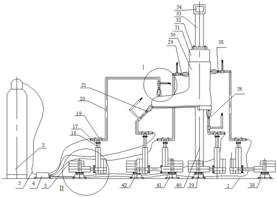
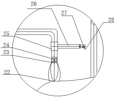
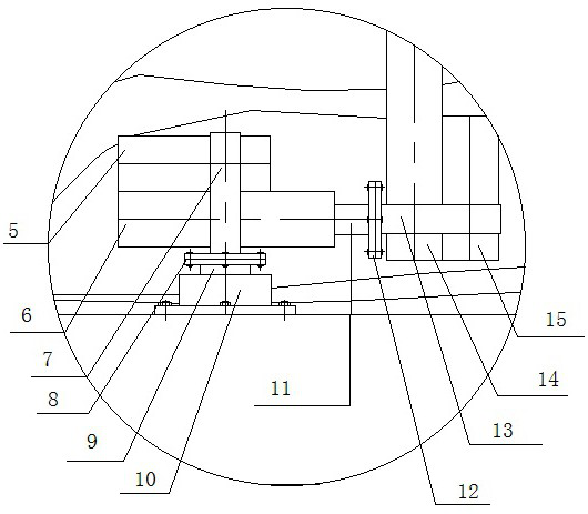
The invention provides an automatic test device for the flame retardant property of a firefighter protective boot and a use method.The test device comprises a cantilever beam, a foot model is hoisted under the cantilever beam, a protective boot sample is worn outside the foot model, moving devices are arranged under the protective boot sample, the tail end of each moving device is connected with a combustor, flaming ports of the five combustors are respectively opposite to the upper surface of the front end of the protective boot sample, the junction of the front end of the protective boot sample and the boot sole, the position under the boot sole of the protective boot sample, the position right in front of the boot leg of the protective boot sample and the position right behind the boot leg of the protective boot sample. The combustors are supported by a mechanical structure, flame shaking can be prevented, it is ensured that the inner flame tip of the flame makes contact with a sample, the distance is kept stable, the requirement that the flame inclines by 90 degrees or 45 degrees is met, timing, observation and judgment are all automatic, the environment where detection personnel are located is improved, and the test detection quality and efficiency are improved.

Description

technical field [0001] The invention belongs to the technical field of fire-fighting product testing equipment and methods, and in particular relates to an automatic test device for the flame-retardant performance of firefighter protective boots and a method for using it. Background technique [0002] Now the flame retardant performance test of fireman's protective boots is carried out manually by hand-held Bunsen burner operation. The protective boots sample is placed on the bench, and the burner is ignited to adjust the flame height to 75mm. The flame is 90 ° or 45 ° against the protective boots. The sample stipulates that five burning points should be left after contacting and burning for 12s. The self-extinguishing time of each burning position after leaving the fire should not exceed 2s. The damage length of each test position should not exceed 100mm, and there should be no melting, dripping or peeling. . Because the hand-held Bunsen burner is operated by hand, it is e...

Claims


Application Information

Patent Timeline
Patent Type & Authority Applications(China)
IPC IPC(8): G01N31/12
CPCG01N31/12
Inventor 邓小波魏中欣刘建志孙洋刘保龙
Owner SHANDONG INST FOR PROD QUALITY INSPECTION
Why Eureka
Try Eureka