
Optical axis debugging method of three-axis stabilized platform with rolling ring

A technology of three-axis stabilization and debugging method, applied in optics, optical components, installation, etc., can solve problems such as crosshair target alignment accuracy, and achieve the effect of improving tracking accuracy, improving zero position accuracy, and ensuring tracking accuracy.

Pending Publication Date: 2021-12-03
HEBEI HANGUANG HEAVY IND
View PDF0 Cites 0 Cited by
  • Summary
  • Abstract
  • Description
  • Claims
  • Application Information

AI Technical Summary

Problems solved by technology

[0004] In order to solve the above-mentioned technical problems, the present invention proposes a method for adjusting the optical axis of a three-axis stable platform with a rolling ring, in order to solve the problem of optical axis adjustment of a three-axis stable platform with a rolling ring in the prior art. Technical issues with reticle targeting and poor alignment accuracy

Method used


Image

  • Optical axis debugging method of three-axis stabilized platform with rolling ring
  • Optical axis debugging method of three-axis stabilized platform with rolling ring
  • Optical axis debugging method of three-axis stabilized platform with rolling ring

Examples


Embodiment Construction

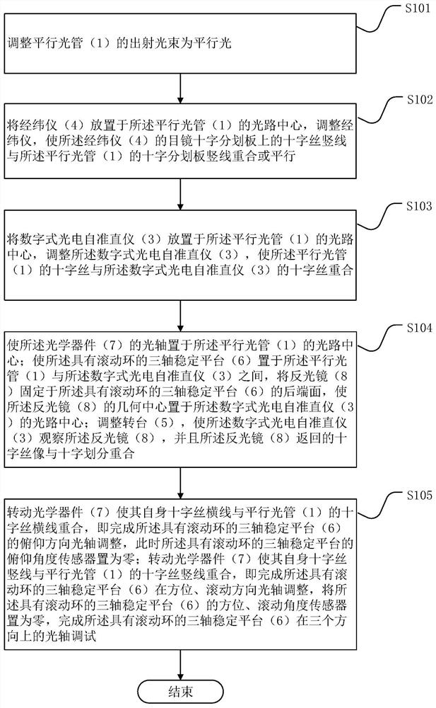
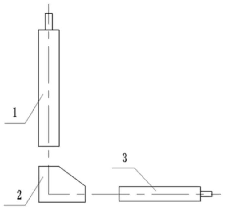
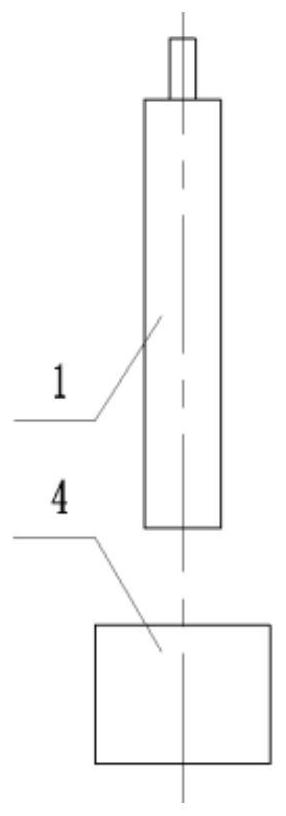
[0019] combine first figure 1 A method for adjusting the optical axis of a three-axis stable platform with a rolling ring according to an embodiment of the present invention is described. Such as figure 1 , 4 As shown, the optical axis debugging method includes the following steps:

[0020] Step S101: adjusting the outgoing light beam of the collimator 1 to be parallel light by the pentaprism;

[0021] Step S102: Place the theodolite 4 at the center of the optical path of the collimator 1, adjust the theodolite 4 to zero horizontally, and adjust the collimator 1 so that its cross reticle is in line with the eyepiece of the theodolite 4 Cross reticle cross overlap or parallel;

[0022] Step S103: placing the digital photoelectric autocollimator 3 in the center of the optical path of the collimator 1, adjusting the digital photoelectric autocollimator 3 so that the cross hair of the collimator 1 is aligned with the digital The reticle of type photoelectric autocollimator 3 ...


PUM


Abstract

The invention provides an optical axis debugging method of a three-axis stabilized platform with a rolling ring. The method comprises the following steps: an emergent light beam of a collimator is adjusted to be parallel light; the vertical line of the cross wire on the cross reticle of the eyepiece of the theodolite is enabled to coincide with or be parallel to the vertical line of the cross reticle of the collimator; a digital photoelectric autocollimator is adjusted, so that the cross wire of the collimator coincides with the cross wire of the digital photoelectric autocollimator; a reflective mirror is fixed on the rear end face of the three-axis stabilized platform with the rolling ring, so that the geometric center of the reflective mirror is arranged at the optical path center of the digital photoelectric autocollimator; a rotary table is adjusted, so that the digital photoelectric autocollimator observes the reflective mirror, and the cross wire image returned by the reflective mirror coincides with the cross division; and an optical device is rotated to enable the vertical line of the own cross wire to coincide with the vertical line of the cross wire of the collimator. The method improves the precision of the optical axis zero position of the stabilized platform, and guarantees the tracking precision of the stabilized platform during working.

Description

technical field [0001] The invention relates to the technical field of optical axis adjustment, in particular to an optical axis adjustment method for a three-axis stable platform. Background technique [0002] When adjusting the optical axis of a three-axis stabilized platform with a rolling ring or a two-axis stabilized platform with a rolling structure, the conventional adjustment method is to set the collimator target reticle at the focal plane position, and the reticle is basically horizontal and vertical. It can meet the requirements of infinity simulation target. [0003] However, for a three-axis stabilized platform with a rolling ring, or a rolling tilt-type stabilized platform, especially a stable platform with a relatively high requirement for the zero position of the rolling optical axis, the verticality of the crosshair of the collimator usually cannot meet the debugging requirements. In addition, when adjusting the optical axis, conventional collimators use hu...

Claims


Application Information

Patent Timeline
Patent Type & Authority Applications(China)
IPC IPC(8): G02B7/00G02B27/62
CPCG02B7/003G02B27/62
Inventor 李世荣孟凡强安红印潘培娟
Owner HEBEI HANGUANG HEAVY IND
Learn More