
Filling equipment control system based on novel wiring layout

A filling equipment and control system technology, applied in the field of filling equipment control system, can solve problems such as affecting the homogeneity of workshops, consume a lot of time, reduce service life, etc., and achieve the effect of simplifying wiring complexity, improving aesthetics, and facilitating installation

Pending Publication Date: 2021-12-03
GUANGZHOU TECH LONG PACKAGING MACHINERY CO LTD
View PDF0 Cites 0 Cited by
  • Summary
  • Abstract
  • Description
  • Claims
  • Application Information

AI Technical Summary

Problems solved by technology

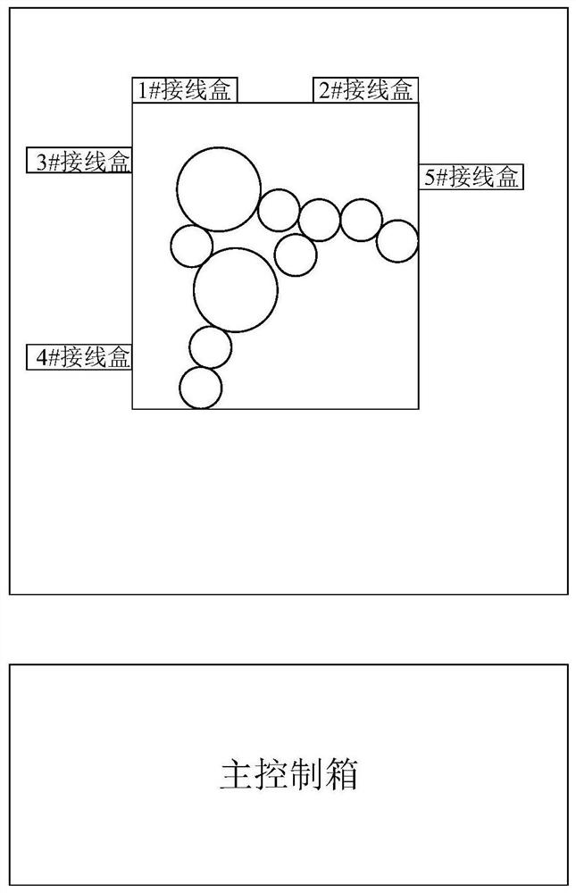
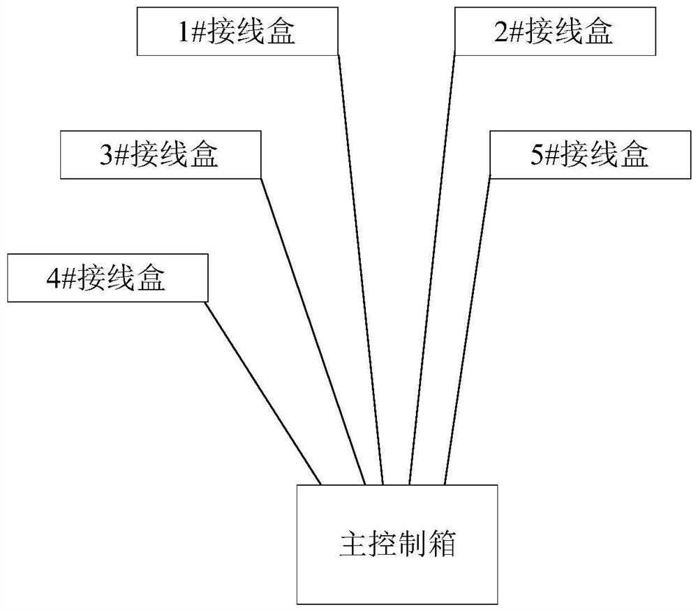
In order to meet the transportation requirements, the existing filling equipment has the following disadvantages after the filling equipment is made into a split type equipment: 1) The electric control box for controlling the filling equipment should be placed outside the filling workshop. The location should be determined according to the customer's factory building. It is difficult to accurately calculate the actual length from the junction box to the electric control box through the cables. If it is too long, it will increase the design cost and affect the aesthetics of the wiring. Connect it back to the electric cabinet, which will cause a mess of cables on the ground, which will affect the homogeneity of the workshop for a long time, and it will be easy to wear and tear on the exposed ground, reducing the service life
2) After the filling equipment is separated, each junction box needs to be rewired to the electric control box, which leads to a heavy workload for the after-sales installers of the filling equipment, and this process takes a lot of time. When the installation time is short, it is easy to cause wiring errors

Method used


Image

  • Filling equipment control system based on novel wiring layout
  • Filling equipment control system based on novel wiring layout
  • Filling equipment control system based on novel wiring layout

Examples


Embodiment Construction

[0030] The present invention will be further described in detail below in conjunction with the accompanying drawings and embodiments. It should be understood that the specific embodiments described here are only used to explain the present invention, but not to limit the present invention. In addition, it should be noted that, for the convenience of description, only some structures related to the present invention are shown in the drawings but not all structures.

[0031] Before discussing the exemplary embodiments in more detail, it should be mentioned that some exemplary embodiments are described as processes or methods depicted as flowcharts. Although the flowcharts describe various operations (or steps) as sequential processing, many of the operations may be performed in parallel, concurrently, or simultaneously. In addition, the order of operations can be rearranged. The process may be terminated when its operations are complete, but may also have additional steps not ...


PUM


Abstract

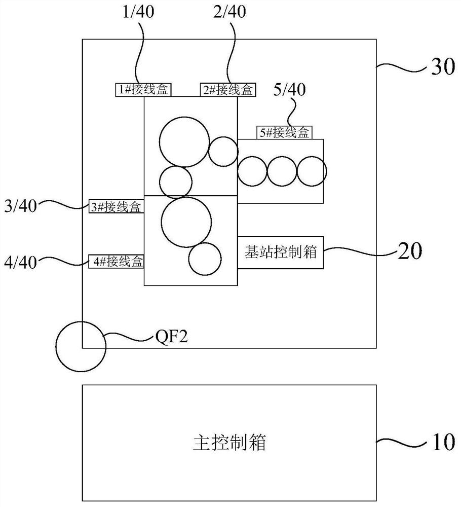
The embodiment of the invention discloses a filling equipment control system based on novel wiring layout. The filling equipment control system comprises a main control box, a base station control box and filling equipment. A plurality of junction boxes are arranged in the filling equipment, the main control box and the base station control box are connected through a cable, and the base station control box is connected with the junction boxes. According to the technical scheme, the base station control box is arranged in the filling equipment, the main control box located outside the workshop is connected with the base station control box only through one cable, each junction box does not need to be connected to the main control box again, overall control over the filling equipment by the main control box is achieved. The number of cables from the main control box to the filling equipment is reduced, the wiring complexity is simplified, and installation of the filling equipment is facilitated.

Description

technical field [0001] The embodiments of the present invention relate to the technical field of electrical equipment, and in particular to a filling equipment control system based on a new wiring layout. Background technique [0002] The layout of electrical wiring on automation equipment is one of the important components of the entire equipment, especially in standard automation equipment such as hot filling. [0003] Hot filling filling equipment is mainly for tea, fruit juice, health drinks and other products. During the hot filling process, the entire filling workshop will be flooded with hot steam. Therefore, the electric control box that controls the filling equipment cannot Placed in the filling workshop to avoid the long-term influence of steam and high temperature on the components on the filling equipment and reduce the service life. In addition, in the process of sea and land transportation, the size of the filling equipment is regulated. The filling equipment ...

Claims


Application Information

Patent Timeline
Patent Type & Authority Applications(China)
IPC IPC(8): G05B19/05
CPCG05B19/054G05B2219/1103
Inventor 林海英
Owner GUANGZHOU TECH LONG PACKAGING MACHINERY CO LTD
Learn More