Automatic pin winding machine

An automatic, frame-based technology, applied in coil manufacturing, etc., can solve problems such as easy to break or break pins, fail to meet production capacity requirements, and slow speed, and achieve high automation, low production cost, and fast working speed. Effect

Pending Publication Date: 2021-12-03
ZHONGSHAN COMPETENT AUTOMATION EQUIP CO LTD
View PDF0 Cites 4 Cited by
  • Summary
  • Abstract
  • Description
  • Claims
  • Application Information

AI Technical Summary

Problems solved by technology

[0003] At present, the foot binding process cannot be fully automated, and manual operations are required, such as the need to manually pull the straight head, etc., the efficiency is extremely low, the speed is very slow, and the production capacity cannot be met.
[0004] In addition, for those inductance coils with relatively small magnetic rings and relatively thick winding wires, it is difficult to wind the wires. The existing winding equipment is easy to break or break the pins, crush the winding wires, and the product qualification rate is low.

Method used


Image

  • Automatic pin winding machine
  • Automatic pin winding machine
  • Automatic pin winding machine

Examples


Embodiment Construction

[0041] In order to enable those skilled in the art to better understand the technical solution of the present invention, the present invention will be further described in detail below in conjunction with the accompanying drawings and specific embodiments.

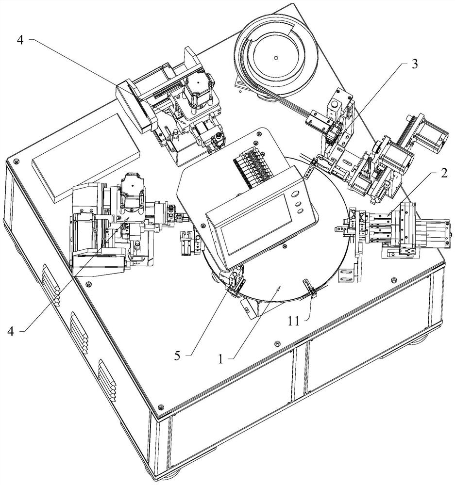
[0042] Such as Figure 1 to Figure 11 A kind of automatic foot-binding machine shown includes:

[0043] The frame is used to install various mechanisms;

[0044] Material transfer mechanism 1, described material transfer mechanism 1 is provided with at least one magnetic ring holder 11 for placing coils, preferably provided with on the magnetic ring holder 11;

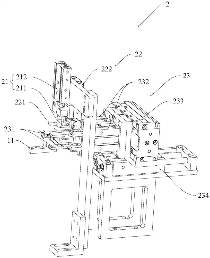
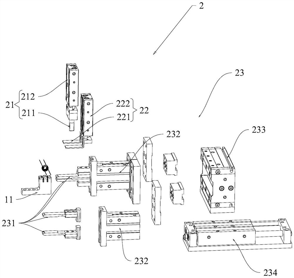
[0045] The winding straightening assembly 2 is used to straighten the winding ends on the magnetic ring to both sides respectively;

[0046] Skeleton dispensing and feeding assembly 3 is used to dispense glue to the skeleton and transfer the skeleton to the magnetic ring so that the magnetic ring and the skeleton are bonded;

[0047] The foot binding assembly 4 ...


PUM


Abstract

The invention discloses an automatic pin winding machine which comprises a rack, a material rotating mechanism, a winding wire straightening assembly, a framework dispensing and feeding assembly and a pin winding assembly. And the pin winding assembly comprises a second jacking assembly used for downwards jacking a coil framework, a winding clamping assembly used for clamping a winding wire end, and a winding driving assembly used for driving the winding clamping assembly to do three-dimensional circular motion so as to wind a winding wire on a coil pin. A magnetic ring fixing seat on the material transferring mechanism automatically conveys a magnetic ring, the winding wire straightening assembly straightens a winding wire on the magnetic ring, the framework dispensing and feeding assembly dispenses glue on the framework and adheres the framework to the magnetic ring, the pin winding assembly winds a winding wire end to a corresponding pin, a material receiving assembly receives materials, the whole process is integrated and automatic, the working speed is high, and the production efficiency is high. The product yield is high, and the production cost is low.

Description

technical field [0001] The invention relates to the technical field of coil foot-binding equipment, in particular to an automatic foot-binding machine. Background technique [0002] The inductance coil is a commonly used electrical component with great demand. The inductance coil usually includes a magnetic ring and a skeleton. The magnetic ring is wound with winding wires. There are 2-4 pins on the skeleton. on, usually wrapped around a pin. When the inductance coil wraps the feet, it is necessary to straighten the ends of the winding wires to both sides respectively, then glue the skeleton, and then wrap the ends of the winding wires on the pins respectively. [0003] At present, the foot binding process cannot be fully automated, and manual operations are required, such as the need to manually pull the straight head, etc., which is extremely inefficient and slow, and cannot meet the requirements of production capacity. [0004] In addition, for those inductance coils wi...

Claims


Application Information

Patent Timeline
Patent Type & Authority Applications(China)
IPC IPC(8): H01F41/10
CPCH01F41/10
Inventor 周珂陈慧廖述艳马细艳黄奇翰熊刚施洋
Owner ZHONGSHAN COMPETENT AUTOMATION EQUIP CO LTD
Why Eureka
Try Eureka