
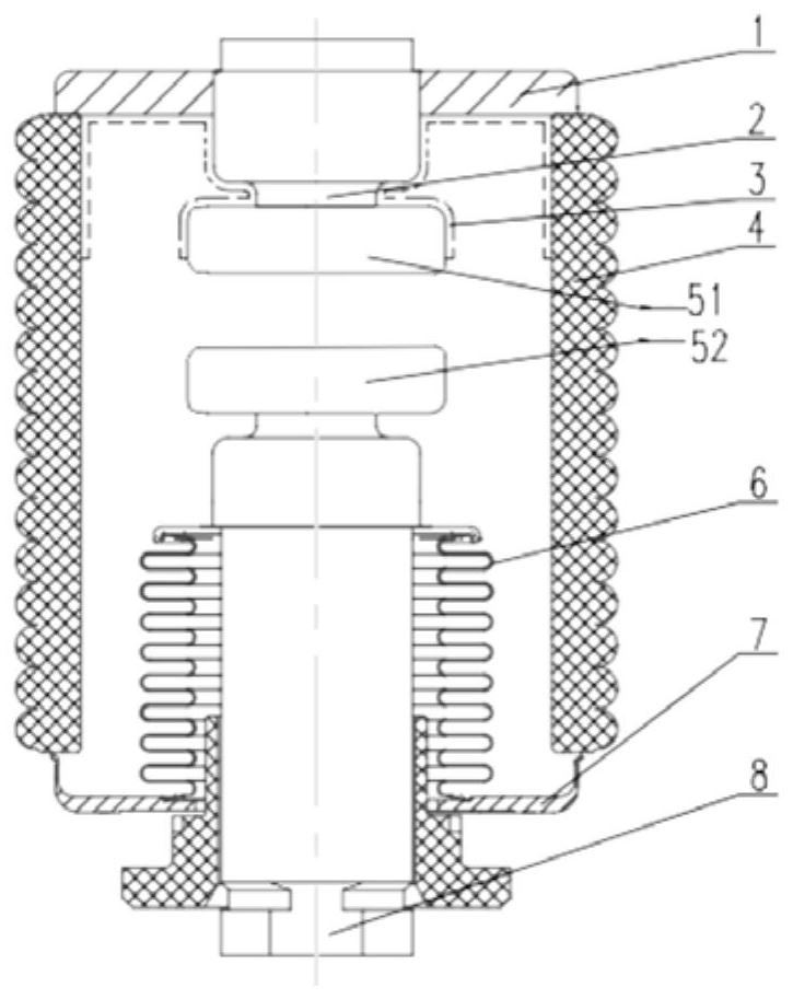
Heat conduction enhanced vacuum arc extinguish chamber

A vacuum interrupter and enhanced thermal conductivity technology, applied in high-voltage air circuit breakers, electrical components, electrical switches, etc., can solve the limitation of the rated current and temperature rise of the interrupter, the selection of contact forms and the optimization design of parameters. and other problems to achieve the effect of improving the heat dissipation effect and increasing the heat transfer path

Pending Publication Date: 2021-12-03
XI AN JIAOTONG UNIV
View PDF14 Cites 0 Cited by
  • Summary
  • Abstract
  • Description
  • Claims
  • Application Information

AI Technical Summary

Problems solved by technology

[0004] At present, the heat dissipation method of the arc extinguishing chamber is still dominated by the one-dimensional conduction method that the internal guide rod transmits to both ends. Under this method, the rated current and temperature rise heat that the arc extinguishing chamber can carry are limited. The requirements for the current carrying and breaking capacity of the arc chamber, the selection of the contact form and the optimal design of parameters also have great constraints

Method used


Image

  • Heat conduction enhanced vacuum arc extinguish chamber

Examples


Embodiment Construction

[0017] In order to enable those skilled in the art to better understand the solutions of the present invention, the following will clearly and completely describe the technical solutions in the embodiments of the present invention in conjunction with the drawings in the embodiments of the present invention. Obviously, the described embodiments are only The embodiments are a part of the present invention, not all embodiments, and are not intended to limit the scope of the present invention. Also, in the following description, descriptions of well-known structures and techniques are omitted to avoid unnecessarily obscuring the concepts disclosed in the present invention. Based on the embodiments of the present invention, all other embodiments obtained by persons of ordinary skill in the art without making creative efforts shall fall within the protection scope of the present invention.

[0018] The schematic diagrams of the structures according to the disclosed embodiments of th...


PUM


Abstract

The invention discloses a heat conduction enhanced vacuum arc extinguish chamber. The arc extinguish chamber comprises a static end cover plate, a static conducting rod, a ceramic insulation heat conduction component, a shell, an upper contact, a lower contact, a movable end cover plate and a movable conducting rod. The static end cover plate is arranged at an opening in the top of the shell, a movable end cover plate is arranged at an opening in the bottom of the shell, the lower end of the static conducting rod penetrates through the static end cover plate and then is connected with an upper contact, the upper end of the movable conducting rod penetrates through the movable end cover plate and then is connected with a lower contact, the upper contact directly faces the lower contact, one end of the ceramic insulation heat conduction component is attached to the outer side of the static conducting rod and the outer side of the upper contact, the other end of the ceramic insulation heat conduction component is attached to the inner wall of the shell, and the arc extinguish chamber can bear large rated current and temperature rise heat.

Description

technical field [0001] The invention belongs to the technical field of vacuum interrupters, and relates to a heat conduction-enhanced vacuum interrupter. Background technique [0002] There are mainly three types of heat sources in vacuum interrupters, namely, heat generated by body resistance, heat generated by eddy current effect, and heat generated by contact resistance. The heat dissipation process mainly relies on the heat transfer from the inside of the arc extinguishing chamber along the guide rod to the external radiator, and then convects heat through the end radiator and the natural space. [0003] The heat dissipation capacity and temperature rise of the interrupter directly determine its rated flow capacity. According to the heat source and heat dissipation characteristics of the vacuum interrupter, the control and optimal design of the temperature rise are mainly reflected in two aspects: reducing heat dissipation and optimizing The contact structure adopts the...

Claims


Application Information

Patent Timeline
IPC IPC(8): H01H33/664H01H33/06
CPCH01H33/664H01H33/06
Inventor 翟小社
Owner XI AN JIAOTONG UNIV
Learn More