
Step-by-step type arc-shaped nail bin

A step-by-step, staple cartridge technology, applied in the field of medical devices, can solve problems such as poor suture effect, reduced degree of cavity curvature, difficulty in forming a circular channel, etc., and achieve the effect of improving suture effect

Pending Publication Date: 2021-12-07
THE WEST CHINA SECOND UNIV HOSPITAL OF SICHUAN
View PDF0 Cites 0 Cited by
  • Summary
  • Abstract
  • Description
  • Claims
  • Application Information

AI Technical Summary

Problems solved by technology

[0004] When the closer is suturing the tissue, the tissue is in contact with the staple cartridge on the closer, and the staples in the staple cartridge are injected into the cavity. For operations that need to cut and suture the cavity and form a channel, it is usually necessary to The auxiliary device is inserted into the baffle in the cavity, and the baffle and the staple cartridge work together on the cavity to suture the cavity. However, when the cavity is not cut and sutured, the cross-sectional shape of the cavity is circular. When the cavity is cut, the cavity is flat. For the cavity of different thickness, the difference between the outer diameter of the cavity and the inner diameter of the cavity is different. If the difference between the outer diameter and the inner diameter of the cavity is large, It will cause the part of the tissue near the outer diameter of the cavity to not be sutured, which will make the suture effect worse, and the cavity wall will be straightened in a curved state after straight-line cutting and suturing, and then the cavity will be sutured. Due to the limitation of the shape, the bending of the cavity depends more on the expansion and contraction of the tissue between two adjacent staples, which reduces the degree of bending of the cavity at the suture site, making it difficult to form a cavity that can be separated by cutting and suturing. A circular channel through which tissue is passed to remove separated tissue from the lumen

Method used


Image

  • Step-by-step type arc-shaped nail bin
  • Step-by-step type arc-shaped nail bin
  • Step-by-step type arc-shaped nail bin

Examples


Embodiment 1

[0031] Embodiment one: see Figure 1-3 as shown,

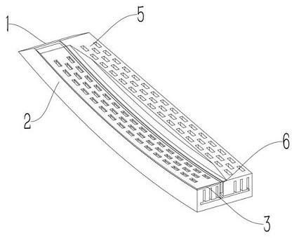
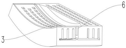
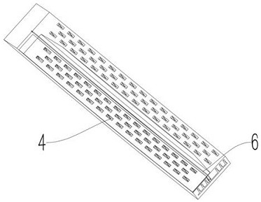
[0032]The step-by-step arc-shaped nail cartridge provided in this embodiment includes a staple cartridge body 1, and the staple cartridge body 1 includes a first closing portion 2, and the first closing portion 2 is used to communicate with the stopper extending into the cavity. The plate fits and sutures the cavity under pressure, and makes the cross-sectional shape of the portion of the cavity that cooperates with the first closing part 2 be arc-shaped during sewing. The step-by-step arc-shaped staple cartridge includes a staple cartridge body 1, and the staple cartridge body 1 includes a first closing portion 2. When the staple cartridge is used to suture the cavity, the portion of the cavity that needs to be formed is placed in the first closing portion. On the closing part 2, a baffle that matches the first closing part 2 is inserted into the patient's cavity, so that the first closing part 2 and the baffle interact to a...

Embodiment 2

[0035] Embodiment two: see Figure 1-3 as shown,

[0036] The difference between this embodiment and Embodiment 1 is that: the first closure part 2 is provided with several first placement holes 4, the first placement holes 4 are used to place staples, and the first placement holes 4 are Multiple rows are arranged, and each row includes several first placement holes 4 , gaps are formed between the first placement holes 4 in the same row, and the gaps in adjacent rows are staggered. Several first placement holes 4 are provided on the first closure part 2, and the staples are placed in the first placement holes 4. When the cavity is sutured, the staples in the first placement holes 4 are pushed out of the first closure. part 2, and the first placement holes 4 are provided in multiple rows, so that when the staples in two adjacent first placement holes 4 on the same row are used to suture the cavity tissue, there is a gap between the two staples so that The tissue at this place...

Embodiment 3

[0038] Embodiment three: see Figure 1-3 as shown,

[0039] The difference between this embodiment and Embodiment 1 and Embodiment 2 is that: the staple cartridge body 1 further includes a second closing portion 5, and the second closing portion 5 is used for applying pressure to suture the lumen. The staple cartridge body 1 also includes a second closing portion 5, which can pressurize and sew the cavity. Suture, and make the first closing part 2 suture the cavity that needs to form the channel, and the second closing part 5 closes and sutures another part of the cavity, and the cavity tissue of the closed suture is convenient to take out from the cavity forming the channel At the same time, the blood loss at the incision of the cavity tissue is effectively reduced.

[0040] As a preferred embodiment, on the basis of the above method, further, the surface of the second closing part 5 for matching with the cavity is a plane. In the operation of suturing the cavity and takin...


PUM


Abstract

The invention relates to a step-by-step type arc-shaped nail bin which comprises a nail bin body, the nail bin body comprises a first closing part, the first closing part is used for being matched with a baffle extending into a cavity and conducting pressure suturing on the cavity, and the cross section of the part, matched with the first closing part, of the cavity is made to be in an arc shape during suturing. According to the scheme, when a cavity is sutured, a cavity part needing to form a channel is placed on the first closing part, and the baffle matched with the first closing part extends into the cavity of a patient, so that the first closing part and the baffle interact to apply pressure to suture cavity tissue, the cross section of the part, matched with the first closing part, of the cavity is in an arc shape, the defect that linear cutting and sewing are adopted for the cavity is overcome, the degree of stretching the cavity needing to form a channel to a flat shape in the sewing process is greatly reduced, the sewing effect is improved, and an annular channel capable of taking the separated tissues out of the cavity is formed in the cavity.

Description

technical field [0001] The invention relates to the technical field of medical devices, in particular to a step-by-step arc-shaped nail cartridge. Background technique [0002] Closer is a device used in medicine to replace manual suturing. The main working principle is to use staples to separate or anastomose tissues, similar to a stapler; according to different scopes of application, it can be divided into skin closers, digestive tract (esophageal, gastrointestinal, etc.) circular closure, rectal closure, circular hemorrhoid closure, circumcision closure, blood vessel closure, hernia closure, lung cutting and suturing device, etc. [0003] Although the current occluder has a good effect on cutting tissue and suturing the incision, the inventors found in actual use that the current occluder still has deficiencies, specifically: [0004] When the closer is suturing the tissue, the tissue is in contact with the staple cartridge on the closer, and the staples in the staple ca...

Claims


Application Information

Patent Timeline
IPC IPC(8): A61B17/072
CPCA61B17/072A61B2017/07271A61B2017/07285
Inventor 郑莹周小驰杨帆王乔王卡娜
Owner THE WEST CHINA SECOND UNIV HOSPITAL OF SICHUAN
Learn More