Bridge crack information fusion method

A fusion method and bridge technology, applied in the detection of bridge cracks and information fusion, can solve the problems of unnatural splicing results, difficulty in deriving the corresponding relationship between the internal information of the fused image, and much noise interference, so as to achieve the true integrity of the spliced ​​image and enhance the image. Stitching effect, stitching image more effects

Active Publication Date: 2019-05-31
XIDIAN UNIV +2
View PDF3 Cites 6 Cited by
  • Summary
  • Abstract
  • Description
  • Claims
  • Application Information

AI Technical Summary

Problems solved by technology

[0008] The spatial domain fusion method is fast and easy to implement, but it has more noise interference, is prone to seam lines or ghosting, and the fusion effect is poor
[0009] The transform domain fusion method can deal with unnatural phenomena and obtain more complete and real results. The fusion effect is better, but the operation is more complicated and the speed is slower.
[0010] The image fusion method is mainly aimed at the contour fusion of the image surface, without considering the information fusion inside the image, and the pixel coordinates and pixel values ​​have to undergo complex processing, which makes it difficult to deduce the corresponding relationship between the information inside the image before and after fusion, and makes it difficult for the fusion of crack information
[0011] In summary, most of the image stitching methods currently proposed have the problems of incompatibility between stitching quality and speed, unnatural stitching results and low accuracy, and there is no accurate and fast method for fusing internal information of images, which affects the practicality of bridge crack detection. application

Method used


Image

  • Bridge crack information fusion method
  • Bridge crack information fusion method
  • Bridge crack information fusion method

Examples


Embodiment Construction

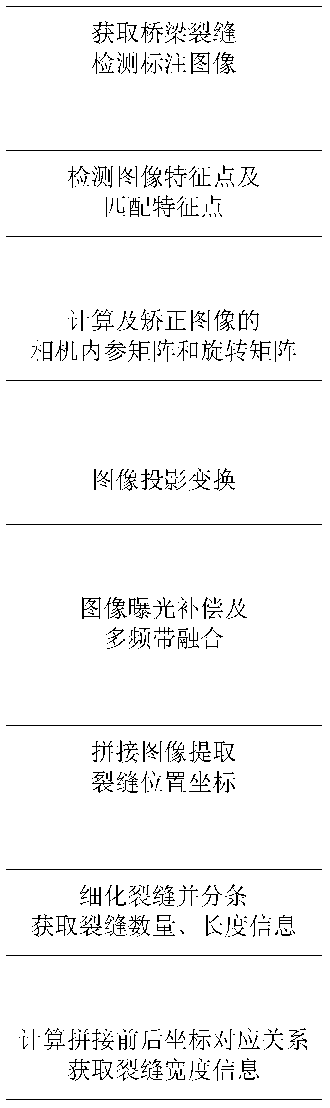
[0042] The embodiments and effects of the present invention will be further described below in conjunction with the accompanying drawings.

[0043] refer to figure 1 , the concrete realization of the present invention is as follows:

[0044] Step 1. Obtain annotated images for bridge crack detection.

[0045] The computer reads a group of bridge images that have undergone bridge crack detection, and obtains the crack position and crack width. Using the RGB three channels of the image, first mark the crack point of each image and within the range of five pixels around it, that is, in the R The channel assigns the corresponding width value of the crack point, assigns 0 to the G channel, and assigns 255 to the B channel; then assigns 255 to the R channel, 0 to the G channel, and 0 to the B channel at the midpoint of each image as the midpoint mark point.

[0046] Step 2. Detect image feature points and match feature points to obtain n groups of matching image pairs.

[0047] ...


PUM


Abstract

The invention discloses a bridge crack information fusion method which mainly solves the problem that an existing image splicing algorithm is poor in bridge crack information fusion accuracy. The implementation scheme comprises the following steps: acquiring a bridge crack detection mark image; detecting image feature points and matching the feature points; calculating a camera internal referencematrix and a rotation matrix of the image according to the image matching feature points, and performing projection transformation on the image; performing exposure compensation and multiband fusion on the projection transformation image to obtain a spliced image; extracting crack position coordinates of the spliced image; refining the cracks and splitting the cracks to obtain the number and length information of the cracks; and calculating a coordinate corresponding relation before and after splicing to obtain crack width information. According to the invention, image splicing and informationfusion of crack quantity, length and width are carried out on the bridge crack detection mark image through the image processing technology, bridge crack information after image splicing can be extracted, and the method is high in practicability, accuracy and reliability and can be used for detecting various bridge cracks.

Description

technical field [0001] The invention belongs to the technical field of testing, and in particular relates to an information fusion method, which can be used to detect bridge cracks. Background technique [0002] For bridge crack detection, the method is changing from manual detection to automatic image detection. At present, there are many automatic crack detection algorithms, which can detect the cracks in the bridge surface image captured by the camera, and measure the position, quantity, length, width and other information of the cracks. However, one problem with automatic bridge detection is that the camera shooting range is limited, and most of the detection results are partial, making it difficult to assess the damage of a complete structural area of ​​the bridge. Therefore, it is necessary to take multiple sets of images of a complete structural area of ​​the bridge, perform image stitching and information fusion, and obtain global crack detection results, so as to b...

Claims


Application Information

Patent Timeline
Patent Type & Authority Applications(China)
IPC IPC(8): G06T3/40G06T7/80G06T7/00G06K9/46G01N21/88
Inventor 杜建超李红丽李云松汪小鹏郭祥伟栗一鸣
Owner XIDIAN UNIV
Why Eureka
Try Eureka