
Rotator cuff prosthesis, preparation method thereof and rotator cuff prosthesis device

A prosthesis and rotator cuff technology, applied in the field of medical devices, can solve problems such as filler leakage, rotator cuff balloon failure, and limited service life of rotator cuff prosthesis

Pending Publication Date: 2021-12-07
SHANGHAI ENDOPHIX CO LTD
View PDF7 Cites 0 Cited by
  • Summary
  • Abstract
  • Description
  • Claims
  • Application Information

AI Technical Summary

Problems solved by technology

However, the rotator cuff prosthesis is placed between the tendon and the humerus, and the frequent friction with the humeral head will cause the rotator cuff prosthesis to fail due to damage, tearing, fracture, etc., greatly limiting the service life of the rotator cuff prosthesis
For example, due to frequent friction, the rotator cuff balloon may be damaged, causing the filled filling to leak from the damaged place, causing the rotator cuff balloon to no longer provide support and fail

Method used


Image

  • Rotator cuff prosthesis, preparation method thereof and rotator cuff prosthesis device
  • Rotator cuff prosthesis, preparation method thereof and rotator cuff prosthesis device
  • Rotator cuff prosthesis, preparation method thereof and rotator cuff prosthesis device

Examples


preparation example Construction

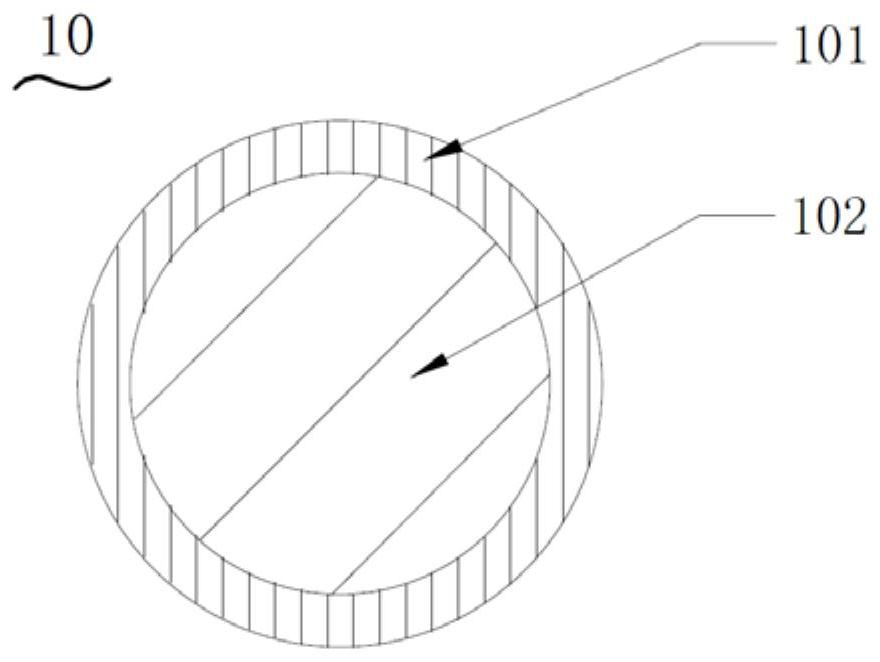
[0101] Examples of materials for the preparation of the above-mentioned unprotected prosthetic body include ultra-high molecular weight polyethylene, high-density polyethylene, polypropylene, polyethylene terephthalate, and nylon. It can be braided and formed by composite yarn, which is composed of several monofilaments, and one monofilament is composed of multiple threads.

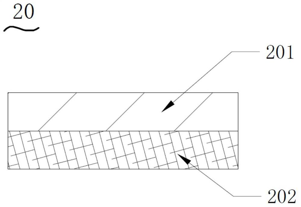
[0102] The prosthetic sleeve obtained by adding a protective structure (preferably a coating structure) to the main body of the prosthetic sleeve is required to have good wear resistance, for example, it needs to withstand at least 5 million times of friction.

[0103] When the rotator cuff prosthesis does not include a prosthesis cover, the outer surface of the prosthesis needs to be provided with the protective structure of the present invention. At this time, the protective structure can be used as a surface layer of the prosthesis (for example, as a protective coating), and the surface layer includes ...

Embodiment 1

[0187] Example 1. Preparation of Braided Silk with PTFE Coating (for the Preparation of Balloons)

[0188] Using two winding devices, one end will convey the 20D ultra-high molecular weight polyethylene fiber, and pass through the solution tank (1 meter long) filled with aqueous polytetrafluoroethylene dispersion emulsion (solid content 30%) at a speed of 5m / min, after that Through the 120°C high-temperature blast channel (channel length 10 meters), after the water is evaporated and dried, the coating thickness is about 80 microns, and the fiber filaments enter the other end for winding, which is worth braided filaments with PTFE coating.

[0189] The braided yarn obtained in this embodiment forms a coating structure on its outer surface layer, and is braided to obtain a braided fabric. At this time, the surface of the braided fabric also has a PFTE protective layer correspondingly, which can be used as a protective structure.

Embodiment 2

[0190] Embodiment 2. Preparation of braided silk with PTFE coating (for preparing balloon cover)

[0191] Use the winder to rewind the 20D ultra-high molecular weight polyethylene fiber, place the solution tank filled with water-based polytetrafluoroethylene dispersion emulsion (solid content 30%) on the wire passage of the winder, and rewind the braided silk The solution is passed through the drum, and the rewinding speed is 30m / min, so that the surface of the braided yarn is evenly coated with polytetrafluoroethylene emulsion, and the coating thickness is about 100 microns. After the coating is completed, put a drum of yarn into an oven and heat it at 80°C Dry for 60 minutes to completely volatilize the moisture, and the coating is formed to obtain a PTFE-coated braided wire.

[0192] The braided yarn obtained in this embodiment forms a coating structure on its outer surface layer, and is braided to obtain a braided fabric. At this time, a PTFE protective layer is correspond...


PUM


Abstract

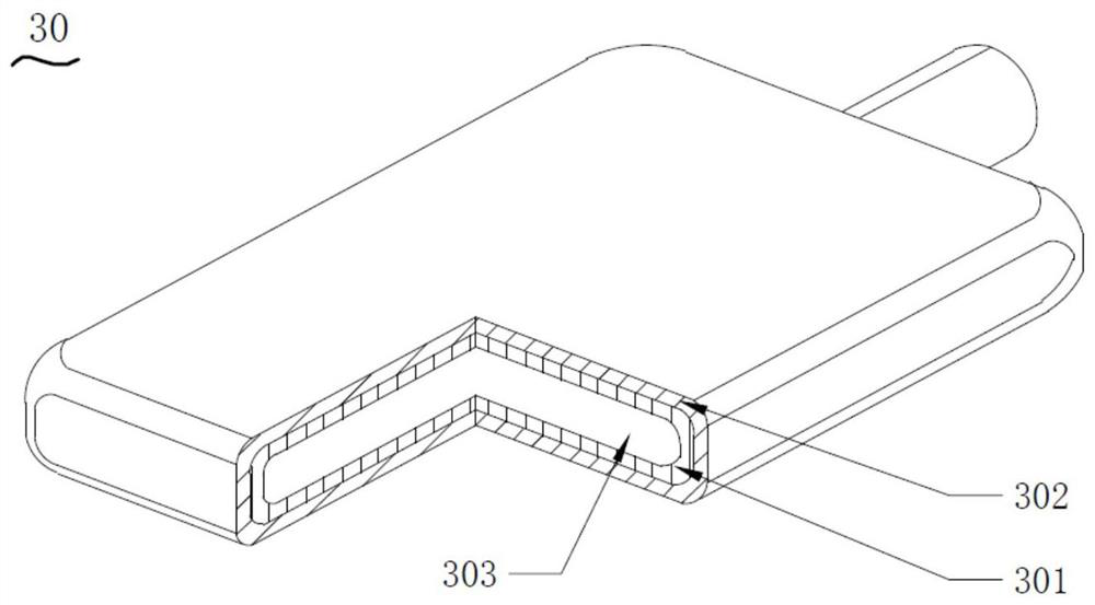
The invention relates to a rotator cuff prosthesis. According to the rotator cuff prosthesis, a protective structure with a low friction coefficient is arranged on the outer surface of the rotator cuff prosthesis, so that the effect of improving the wear resistance of the rotator cuff prosthesis is achieved, and the service life of the rotator cuff prosthesis can be greatly prolonged. The protective structure may be a coating structure, a membrane structure, or a combination of the two. The rotator cuff prosthesis comprises a selectable prosthesis sleeve, the prosthesis sleeve can be arranged outside the prosthesis in a sleeving mode, and after the rotator cuff prosthesis is implanted into a body, the prosthesis sleeve can provide a proper movable space for the prosthesis while protecting the prosthesis, so that the rotator cuff prosthesis can adapt to skeleton tissues in a rotator cuff in a self-adaptive mode. When the prosthesis sleeve is included, the protective structure is arranged on the outer surface of the prosthesis sleeve. The invention further provides a preparation method of the rotator cuff prosthesis and a rotator cuff prosthesis device.

Description

technical field [0001] The invention relates to the technical field of medical devices, in particular to a rotator cuff prosthesis, a preparation method thereof and a rotator cuff prosthesis device. Background technique [0002] The rotator cuff is the muscle-tendon structure that connects the scapula to the head of the humerus and is located on the outer layer of the shoulder joint capsule and the inner layer of the deltoid muscle. The rotator cuff is composed of anterior rotator cuff (subscapularis), upper rotator cuff (supraspinatus), and posterior rotator cuff (infraspinatus and teres minor). It also has the following main functions: it can stabilize the position of the humeral head on the glenoid, and avoid pain caused by the humeral head moving up and hitting the acromion. Therefore, the rotator cuff plays an extremely important role in maintaining the stability of the shoulder joint and in the process of shoulder joint movement. [0003] However, with age, long-term...

Claims


Application Information

Patent Timeline
Patent Type & Authority Applications(China)
IPC IPC(8): A61F2/08
CPCA61F2/08A61F2240/001
Inventor 陈晓刘琛葛亮
Owner SHANGHAI ENDOPHIX CO LTD
Learn More