Eureka AIR delivers breakthrough ideas for toughest innovation challenges, trusted by R&D personnel around the world.

Mask device

A mask and spout technology, applied in respiratory protection devices, clothing, respiratory protection containers, etc., can solve the problems of increased air supply fan vibration, increased air flow distance, inconvenient breathing for users, etc. Noise, smooth breathing effect

Active Publication Date: 2021-12-07
LG ELECTRONICS INC
View PDF9 Cites 0 Cited by
  • Summary
  • Abstract
  • Description
  • Claims
  • Application Information

AI Technical Summary

Problems solved by technology

[0008] However, according to prior art 1, the air filtered by the air cleaner is directly supplied to the user, so there is a problem of the user's pain due to the wind pressure discharged from the air cleaner. breathing problems
[0009] In addition, the supply amount of air supplied through the air inlet corresponds to the number of revolutions of the blower fan, so as the number of revolutions of the blower fan increases, the air The amount of supply also increases, but there is a problem that the vibration caused by the blower fan also increases together
[0010] According to the prior art 2, since the suction fan is located in front of the air passage part, there is a problem that the length of the mask in the front-rear direction increases
[0011] In addition, due to the increased length in the front-to-back direction, the length in the front-to-back direction of the flow space formed above the air passage portion also increases together, so that there is an increase in the flow distance of the air. And the problem of increased flow resistance
[0012] In addition, since the flow distance of the air increases, there is a problem that the time from the operation of the suction fan until it is supplied to the user increases

Method used


Image

  • Mask device
  • Mask device
  • Mask device

Examples


Embodiment Construction

[0046] Hereinafter, the mask device of the embodiment of the present invention will be described in detail with reference to the accompanying drawings.

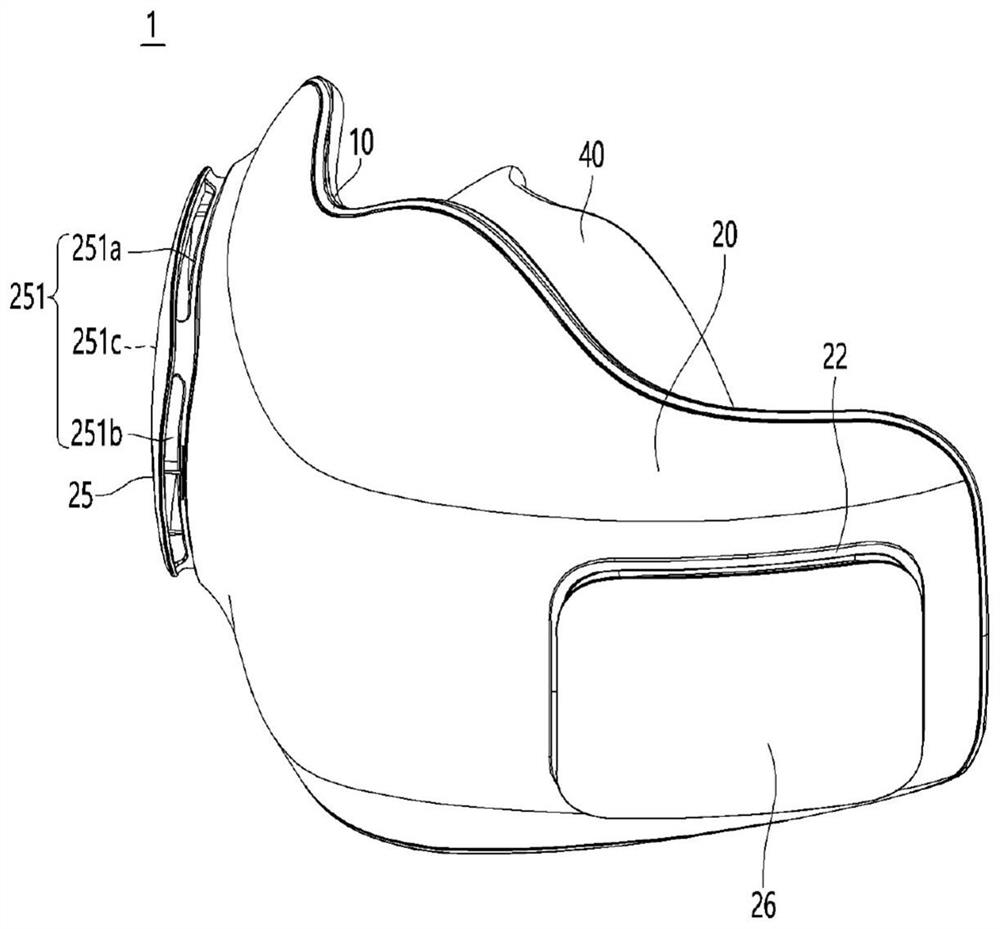
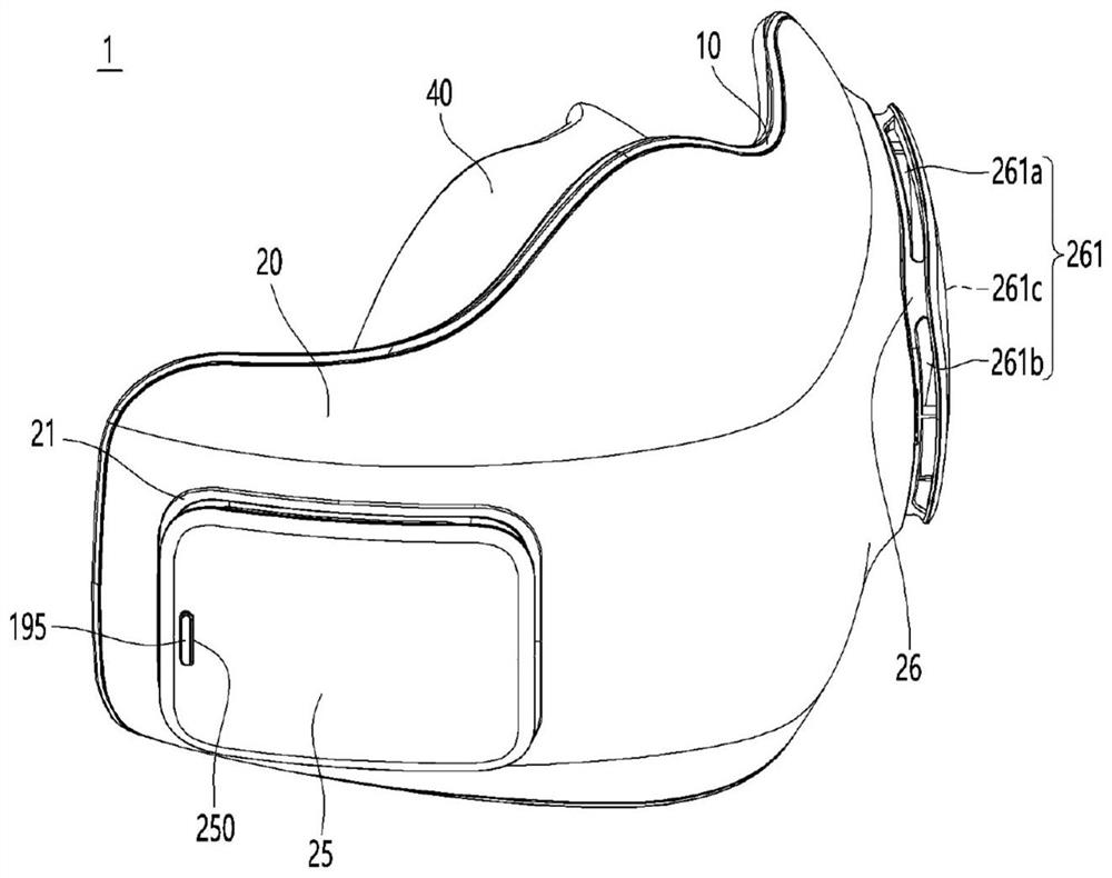
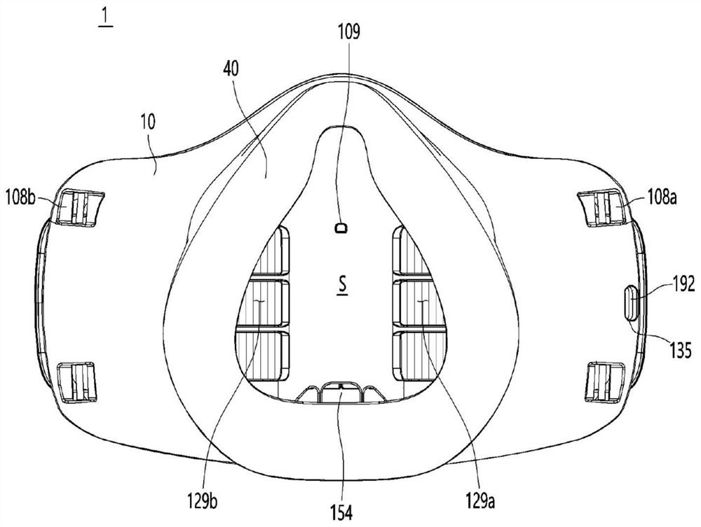
[0047] figure 1 It is the left side perspective view of the mouth mask device of the embodiment of the present invention, figure 2 It is the right side perspective view of the mouth mask device of the embodiment of the present invention, image 3 It is the rear view of the mouth mask device of the embodiment of the present invention, Figure 4 It is the bottom view of the mask device of the embodiment of the present invention.

[0048] refer to Figure 1 to Figure 4 , The mask device 1 of the embodiment of the present invention may include a mask body 10 and a mask body cover 20 combined with the mask body 10 .

[0049] The mask body 10 and the mask body cover 20 can be combined in a detachable manner. By combining the mask body 10 and the mask body cover 20 , an internal space can be formed between the mask body 10 and...


PUM


Abstract

The invention relates to a mask device. The mask device according to an embodiment of the present invention comprises: a mask body having an air passage part formed on the front surface thereof; a sealing part mounted on the back surface of the mask body, the sealing part defining a breathing space communicating with the discharge port of the air passage part and accommodating the mouth and nose of the user; a fan module mounted on a front surface of the mask body corresponding to a suction port of the air passage portion, the fan module suctioning outside air to supply the outside air to the air passage portion; and a mask body cover coupled to the front surface of the mask body so as to cover the fan module and the air passage portion, the mask body cover having an air flow path formed inside the air passage portion, the air flow path allowing air sucked in by the fan module to flow therethrough. A concavo-convex portion is formed on at least a portion of a surface of the air passage portion that is in contact with the outside air flowing along the air flow path.

Description

technical field [0001] The present invention relates to mask devices. Background technique [0002] Generally speaking, a mask is a device that covers the user's nose and mouth in order to avoid inhalation of germs, dust, etc., or droplet transmission caused by viruses or bacteria. [0003] The mask is tightly attached to the user's face in order to cover the user's nose and mouth. The mask filters germs, dust, and the like contained in the air flowing into the user's nose and mouth, and allows the filtered air to flow into the user's mouth and nose. Air and germs, dust, etc. contained in the air pass through the body of the mask including the filter, and germs, dust, etc. are filtered by the body of the mask. [0004] However, since the outside air flows into the user's nose and mouth after passing through the body of the mask, the air that the user spits out also flows out after passing through the body of the mask, thereby causing a problem that the user cannot breathe ...

Claims


Application Information

Patent Timeline
Patent Type & Authority Applications(China)
IPC IPC(8): A62B18/02A62B7/10A62B7/00A41D13/11
CPCA62B18/025A62B7/10A62B7/00A41D13/1176A41D13/1107A62B18/006A62B18/003A62B18/08A62B23/02A62B18/02
Inventor 金兑埈朴正宅金昊重崔硕浩李建旺崔致英
Owner LG ELECTRONICS INC
Why Eureka
Eureka Blog
Learn More