
Welding circuit and control method thereof

A welding circuit and controller technology, which is applied in welding equipment, manufacturing tools, arc welding equipment, etc., can solve the problem that the self-excited oscillator cannot accurately control the output energy of electromagnetic induction heating, etc., so as to reduce the design cost and stabilize the welding effect Effect

Pending Publication Date: 2021-12-07
NINGBO WEIE ELECTRONICS TECH CO LTD
View PDF8 Cites 0 Cited by
  • Summary
  • Abstract
  • Description
  • Claims
  • Application Information

AI Technical Summary

Problems solved by technology

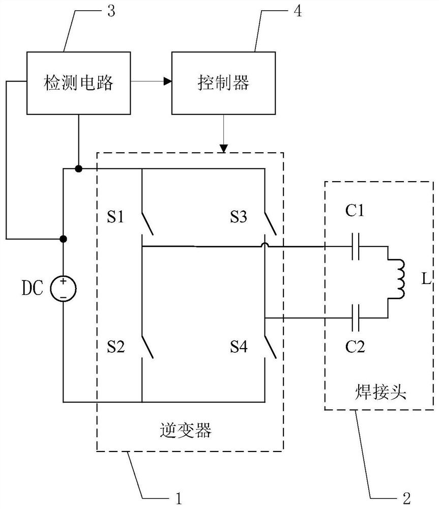
Although the self-excited circuit is simple and reliable, the circuit oscillates freely at the resonance point, and each circuit has individual tolerances, so the output energy is different when oscillating at the resonance point, and the welding effect is different with different output energy; at the same time, the self-excited oscillator The output energy of electromagnetic induction heating cannot be precisely controlled, and the circuit needs to be redesigned for busbars of different widths

Method used


Image

  • Welding circuit and control method thereof
  • Welding circuit and control method thereof
  • Welding circuit and control method thereof

Examples


Embodiment Construction

[0023] The present invention is described below based on examples, but the present invention is not limited to these examples. In the following detailed description of the invention, some specific details are set forth in detail. The present invention can be fully understood by those skilled in the art without the description of these detailed parts. In order not to obscure the essence of the present invention, well-known methods, procedures, procedures, components and circuits have not been described in detail.

[0024] Additionally, those of ordinary skill in the art will appreciate that the drawings provided herein are for illustrative purposes and are not necessarily drawn to scale.

[0025] Meanwhile, it should be understood that in the following description, "circuit" refers to a conductive loop formed by at least one element or sub-circuit through electrical connection or electromagnetic connection. When an element or circuit is said to be "connected to" another eleme...


PUM


Abstract

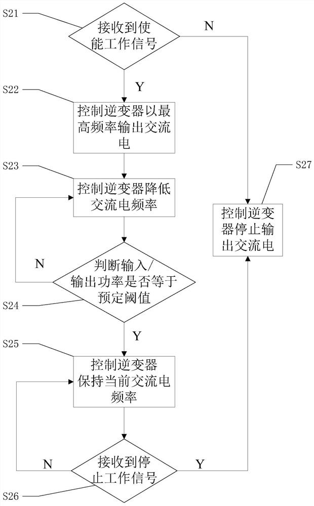
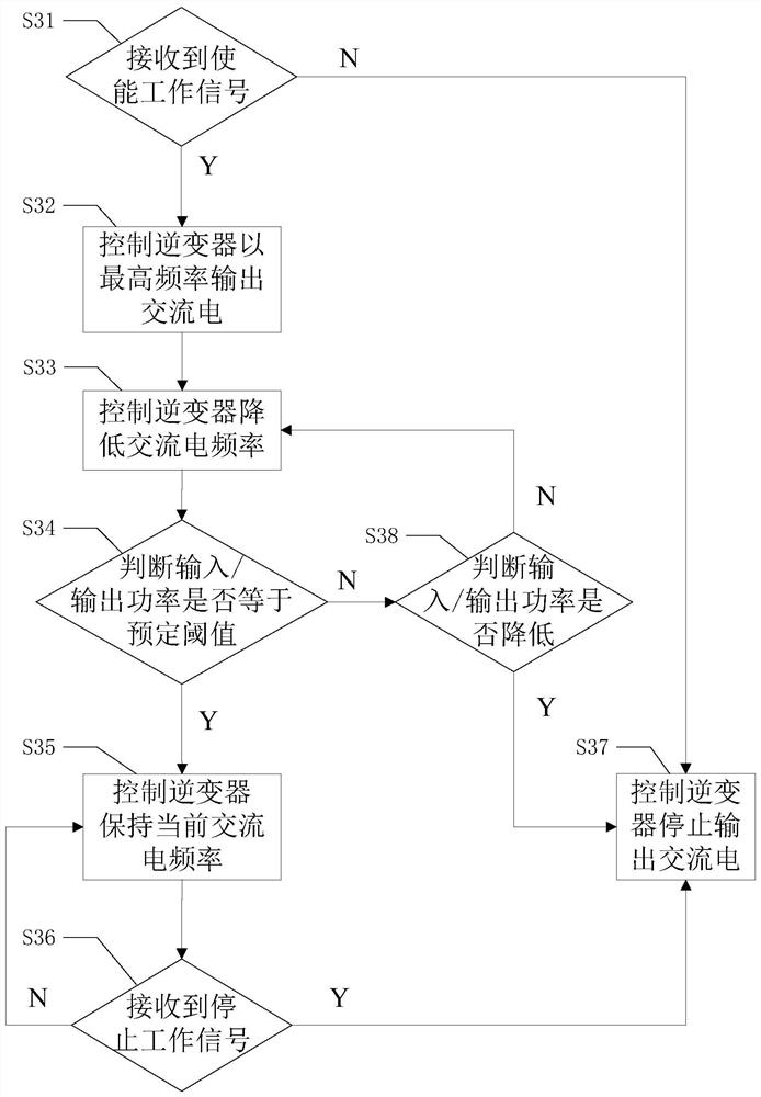
The invention relates to the field of welding, in particular to a welding circuit and a control method thereof. According to the welding circuit and the control method thereof, an inverter, a welding head and a controller are arranged, the controller is used for adjusting the frequency of the alternating current output by the inverter according to the preset control method, the welding circuit works at the output power of a preset threshold value, induction heating energy can be accurately controlled, the welding effect is more stable, the heating effect is consistent for different busbars, a circuit does not need to be redesigned, and the design cost is reduced.

Description

technical field [0001] The invention relates to the field of welding, in particular to a welding circuit and a control method thereof. Background technique [0002] With the progress of society and the development of economy, new clean energy is more and more welcomed by people. As a clean energy, solar energy is more and more widely used. Solar photovoltaic panels are the main components for absorbing solar energy. Each photovoltaic small panel generates current through the photoelectric effect, and the current on each panel needs to be aggregated to the bus bar through grid lines. The current on the row passes through power conversion devices such as inverters for household use or is transmitted to the grid. Gridlines and busbars are typically physically connected by soldering. Welding is usually done by means of electromagnetic induction heating. The prior art is to use a self-excited circuit to realize electromagnetic induction heating. Although the self-excited circ...

Claims


Application Information

Patent Timeline
Patent Type & Authority Applications(China)
IPC IPC(8): B23K9/10
CPCB23K9/1043
Inventor 闫少鹏马涛冯维一余峰
Owner NINGBO WEIE ELECTRONICS TECH CO LTD
Learn More