A sheet metal laser cutting fixture for ship electrical box shell for high-end equipment manufacturing

A laser cutting and equipment technology, applied in manufacturing tools, laser welding equipment, welding equipment, etc., can solve the problem of inability to fix the electric box shell, and achieve the effect of avoiding normal processing, improving quality, and reducing sparks

Active Publication Date: 2022-07-01
苏州涛睿精密钣金科技有限公司
View PDF0 Cites 0 Cited by
  • Summary
  • Abstract
  • Description
  • Claims
  • Application Information

AI Technical Summary

Problems solved by technology

[0003] The purpose of the present invention is to solve at least one of the technical problems existing in the prior art, and to provide a sheet metal laser cutting jig for high-end equipment manufacturing ship electric box shell, which can solve the problem that the electric box shell cannot be quickly fixed

Method used


Image

  • A sheet metal laser cutting fixture for ship electrical box shell for high-end equipment manufacturing
  • A sheet metal laser cutting fixture for ship electrical box shell for high-end equipment manufacturing
  • A sheet metal laser cutting fixture for ship electrical box shell for high-end equipment manufacturing

Examples


Embodiment 1

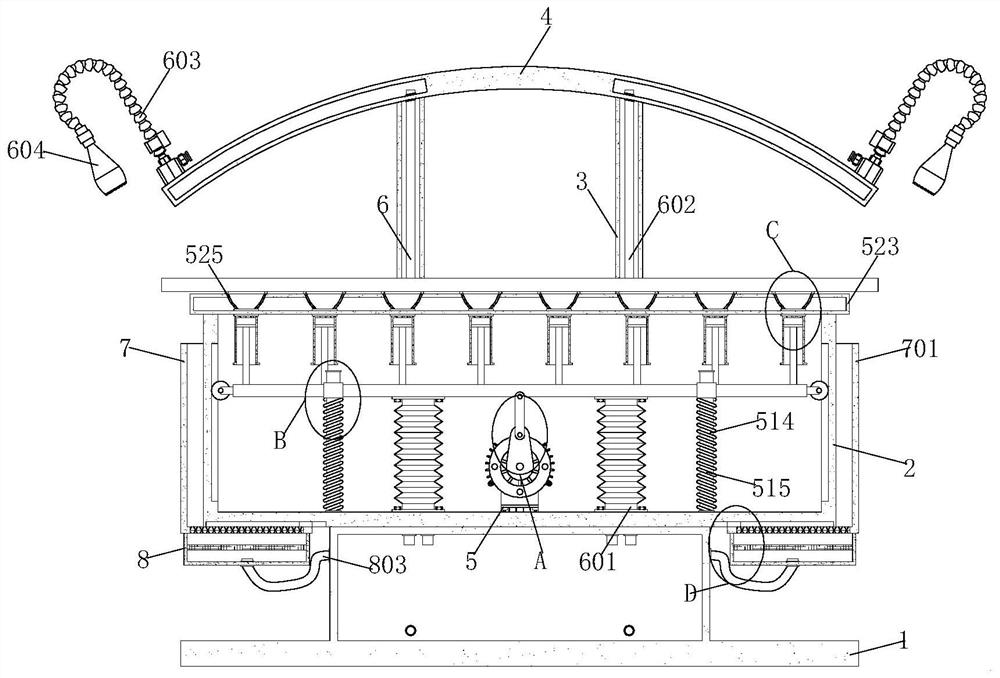
[0036] see Figure 1-8 , the present invention provides a technical solution: a sheet metal laser cutting jig for a marine electrical box shell for high-end equipment manufacturing, including a water tank 1, a fixing mechanism 5, a cooling mechanism 6, a collection mechanism 7 and a filtering mechanism 8, the top of the water tank 1 A placement slot 2 is fixedly installed, the front side of the placement slot 2 is fixedly connected with a water inlet pipe, and one end of the water inlet pipe extends to the inside of the placement slot 2. The rear side of the water tank 1 is fixedly installed with two sets of return plates 3, and two sets of return plates. The top of 3 is fixedly installed with a hollow curved plate 4, and the fixing mechanism 5 is located inside the placing slot 2. The fixing mechanism 5 includes a driving component 51 and an adsorption component 52. The mechanism 6 is arranged on the placement tank 2 and the hollow curved plate 4. The cooling mechanism 6 incl...

Embodiment 2

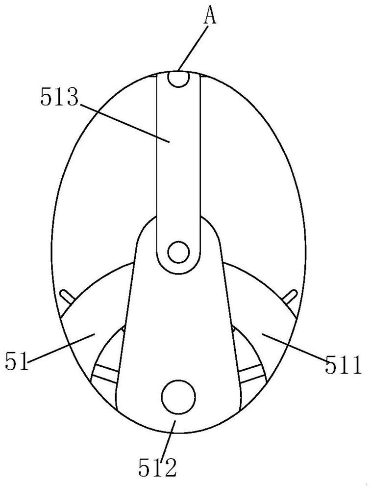
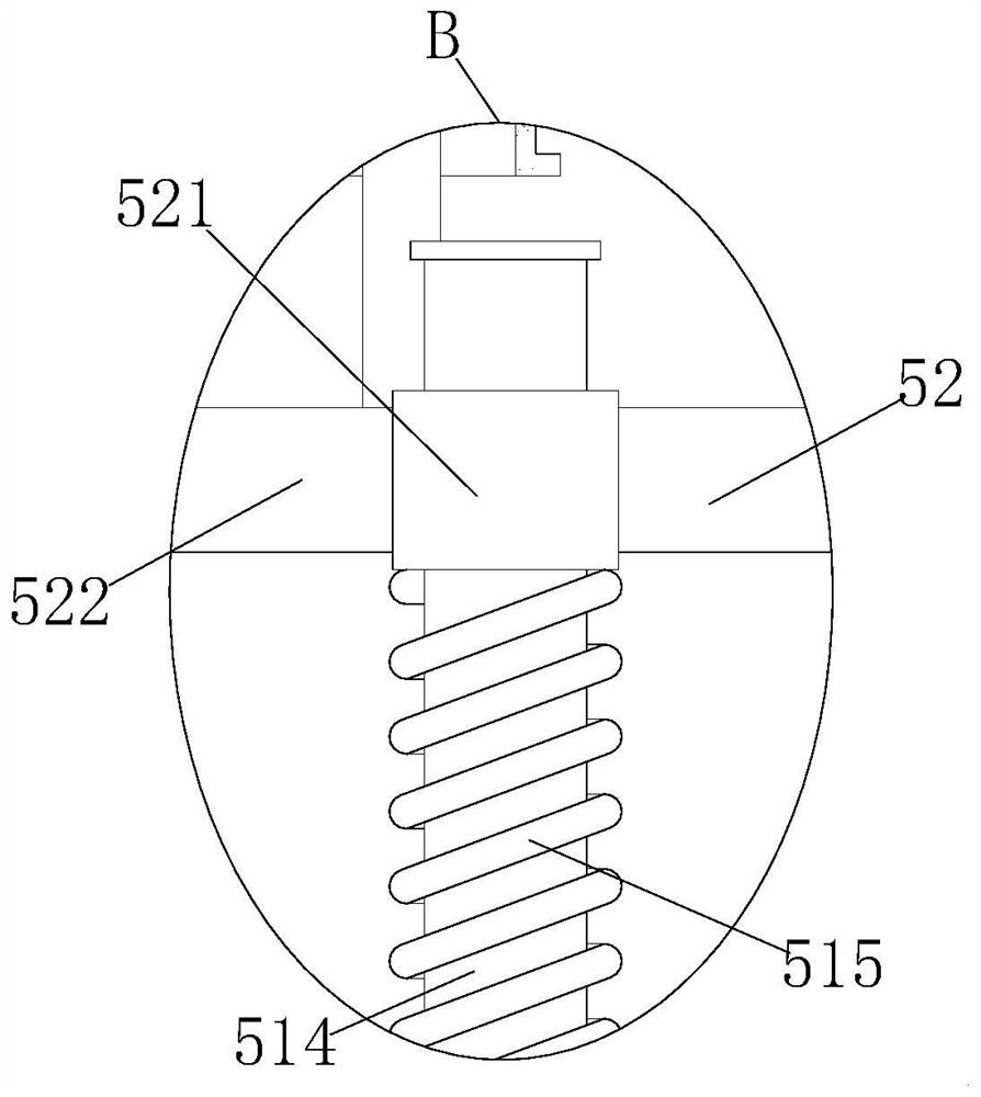
[0038] see Figure 1-8 On the basis of the first embodiment, the drive assembly 51 includes a motor 511, an eccentric wheel 512, a hinge plate 513, a sliding rod 514 and a telescopic spring 515. The number of the sliding rod 514 and the telescopic spring 515 has four groups. The rear side of the eccentric wheel 512 is fixedly connected to the output shaft of the motor 511, the rear side of the hinge plate 513 is hingedly installed with the front side of the eccentric wheel 512, and one end of the four sets of sliding rods 514 They are all fixedly connected to the inner bottom of the placement slot 2. The four groups of telescopic springs 515 are respectively sleeved on the outer walls of the four groups of sliding rods 514. The adsorption assembly 52 includes a sliding rod sleeve 521, a horizontal plate 522, a horizontal hollow plate 523, and a sleeve 524. , suction cup 525, piston 526 and connecting rod 527, the number of sliding rod sleeves 521 has four groups and the four g...


PUM


Abstract

The invention discloses a sheet metal laser cutting fixture for a shell of a marine electrical box for high-end equipment manufacturing, and relates to the technical field of high-end equipment manufacturing. This high-end equipment manufacturing marine electrical box shell sheet metal laser cutting fixture includes a water tank, a fixing mechanism, a cooling mechanism, a collecting mechanism and a filtering mechanism. The top of the water tank is fixedly installed with a placement slot, and the rear side of the water tank is fixedly installed with two Set of paper clips. This high-end equipment manufacturing marine electrical box shell sheet metal laser cutting fixture, through the motor, eccentric, hinge plate, sliding rod, telescopic spring, sliding rod sleeve, horizontal plate, horizontal hollow plate, sleeve, suction cup, piston and The use of the connecting rod can quickly fix the electric box shell, effectively improve the fixing speed of the electric box shell, improve the fixing efficiency, avoid the displacement of the electric box shell during the cutting process, and improve the electric box shell. The stability of the shell cutting improves the machining accuracy of the electric box shell.

Description

technical field [0001] The invention relates to the technical field of high-end equipment manufacturing, in particular to a sheet metal laser cutting jig for ship electrical box shells for high-end equipment manufacturing. Background technique [0002] The existing part of the high-end equipment manufacturing ship electrical box shell sheet metal laser cutting jig cannot quickly fix the electrical box shell, so that the electrical box shell is prone to displacement during the cutting process, thereby reducing the cutting time of the electrical box shell. Stability, resulting in lower accuracy in processing the electrical box shell, and it is easy to affect the laser cutting of the edge of the electrical box shell when fixing the electrical box shell, thus reducing the fluency of cutting the edge of the electrical box shell, reducing the the efficiency of laser cutting. SUMMARY OF THE INVENTION [0003] The purpose of the present invention is to solve at least one of the t...

Claims


Application Information

Patent Timeline
Patent Type & Authority Patents(China)
IPC IPC(8): B23K26/38B23K26/16B23K26/70
CPCB23K26/38B23K26/16B23K26/70
Inventor 管金宝陆晓威周辉宋欢欢
Owner 苏州涛睿精密钣金科技有限公司
Why Eureka
Try Eureka