A fast pneumatic clamping fixture for precision cnc machining

A fast and clamping technology, applied in the direction of manufacturing tools, metal processing equipment, metal processing machinery parts, etc., can solve problems such as easy loosening, shifting, and affecting processing effects, so as to avoid damage, install and fix, and reduce loosening effect of possibility

Active Publication Date: 2022-07-01
深圳市富瑞精密制品有限公司
View PDF7 Cites 0 Cited by
  • Summary
  • Abstract
  • Description
  • Claims
  • Application Information

AI Technical Summary

Problems solved by technology

[0002] General CNC processing usually refers to computer digital control precision machining, CNC processing lathes, CNC processing milling machines, CNC processing boring and milling machines, etc. The main work is to compile processing programs, that is, to convert the original manual work into computer programming. Pneumatic power is often used in CNC processing. There are many kinds of clamping fixtures through pneumatic clamping fixtures. Some pneumatic clamping fixtures mainly drive the upper upper splint to move down through the cylinder structure, and squeeze and install the workpiece on the lower splint on the workbench, etc. Work, but in actual use, due to the existence of defective products, sometimes the extruded workpieces are likely to cause these workpieces to shoot sideways, which is easy to hurt the surrounding workers and other mechanical equipment nearby, and many lower splints pass through the slider For installation, in a long time, it is easy to loosen, which will cause displacement during extrusion and affect the processing effect

Method used


Image

  • A fast pneumatic clamping fixture for precision cnc machining
  • A fast pneumatic clamping fixture for precision cnc machining
  • A fast pneumatic clamping fixture for precision cnc machining

Examples


Embodiment Construction

[0023] In order to make the technical means, creative features, achievement goals and effects realized by the present invention easy to understand, the present invention will be further described below with reference to the specific embodiments.

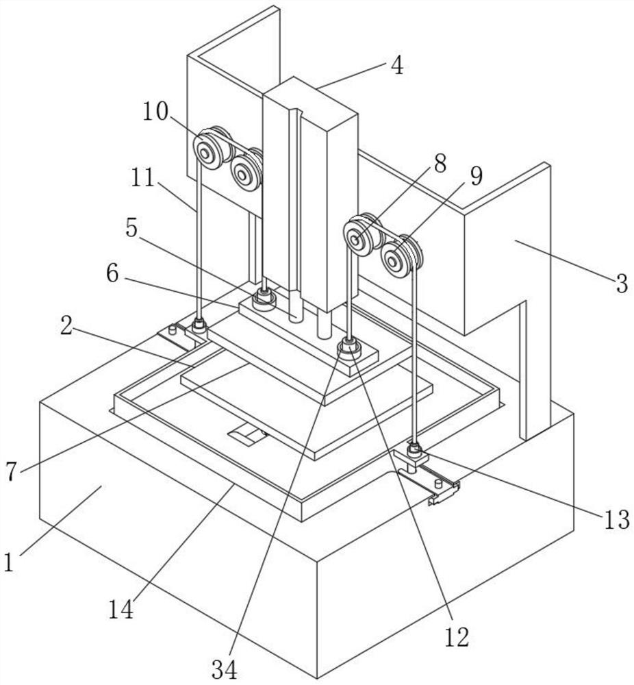
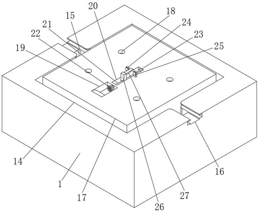
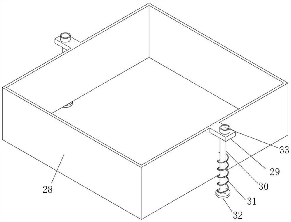
[0024] like Figure 1-5 As shown, a precision CNC machining fast pneumatic clamping fixture includes a control body 1, a rectangular receiving slot 14 is arranged on the control body 1, a rectangular protective plate 28 is arranged in the rectangular receiving slot 14, and the control body 1 is located in a rectangular shape. A rear bracket 3 is arranged on the rear side of the receiving slot 14 , a middle worktable 17 is arranged on the control body 1 at an inner position of the rectangular receiving slot 14 , a lower splint 2 is arranged on the middle table 17 , and a rear bracket 3 is arranged on the rear bracket 3 . Cylinder 4, a pneumatic shaft 5 is arranged in the cylinder 4, an upper mounting plate 6 is arranged below the pneu...


PUM


Abstract

The invention discloses a precision CNC machining rapid pneumatic clamping fixture, comprising a control body, a rectangular receiving groove is arranged on the control body, a rectangular protective plate is arranged in the rectangular receiving groove, and the control body is located at a position on the control body. The rear side of the rectangular storage slot is provided with a rear support, the control body is provided with a middle worktable at the inner side of the rectangular storage slot, the middle worktable is provided with a lower splint, and the rear support is provided with a cylinder A pneumatic shaft is arranged in the cylinder, and an upper mounting plate is arranged below the pneumatic shaft. The invention relates to a precision CNC machining fast pneumatic clamping fixture, which belongs to the field of fixtures, and can protect the workpiece by providing a rectangular protective plate and other structures to avoid projections during extrusion and damage to workers or equipment. In addition, the rectangular protective plate is easy to disassemble, and the installation is more stable through the provided wedge-shaped block structure to avoid loosening.

Description

technical field [0001] The invention relates to the field of fixtures, in particular to a fast pneumatic clamping fixture for precision CNC machining. Background technique [0002] Generally, CNC machining usually refers to computer digital control precision machining, CNC machining lathes, CNC machining milling machines, CNC machining boring and milling machines, etc. The main job is to compile machining programs, that is, to convert the original manual work into computer programming. Pneumatic is often used in CNC machining There are various types of pneumatic clamping fixtures. Some pneumatic clamping fixtures mainly use the cylinder structure to drive the upper upper splint to move down, and squeeze and install the workpiece on the lower splint on the worktable, etc. However, in actual use, due to the existence of defective products, sometimes the extruded workpieces may easily cause these workpieces to project sideways, which may easily hurt the surrounding workers and ...

Claims


Application Information

Patent Timeline
Patent Type & Authority Patents(China)
IPC IPC(8): B23Q3/08B23Q11/08
CPCB23Q3/08B23Q11/08
Inventor 王蕾王建翎
Owner 深圳市富瑞精密制品有限公司
Why Eureka
Try Eureka