Cutting fluid treatment equipment for numerical control machine tool

A technology for processing equipment and CNC machine tools, which is applied to metal processing equipment, metal processing machinery parts, maintenance and safety accessories, etc. It can solve the problems of poor processing effect of cutting fluid, achieve long-term and effective treatment, and avoid filter damage and blockage , Continuous and effective cooling effect

Inactive Publication Date: 2021-12-07
刘秀福
View PDF0 Cites 0 Cited by
  • Summary
  • Abstract
  • Description
  • Claims
  • Application Information

AI Technical Summary

Problems solved by technology

[0004] The purpose of the present invention is to solve the problem of poor cutting fluid treatment effect in the prior art, and propose a kind of cutting fluid treatment equipment for CNC machine tools

Method used


Image

  • Cutting fluid treatment equipment for numerical control machine tool
  • Cutting fluid treatment equipment for numerical control machine tool
  • Cutting fluid treatment equipment for numerical control machine tool

Examples


Embodiment

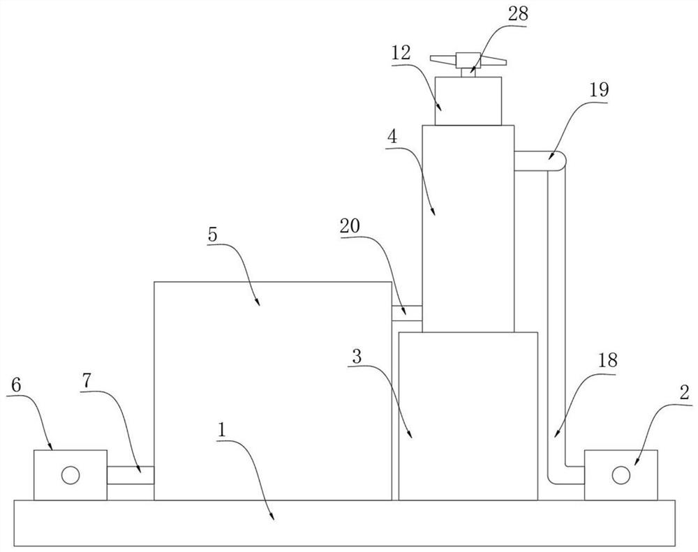
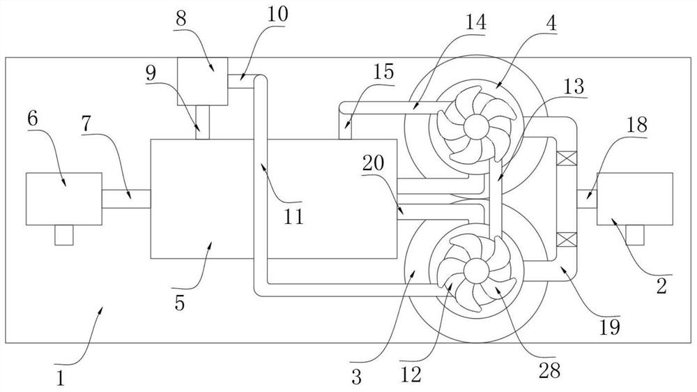
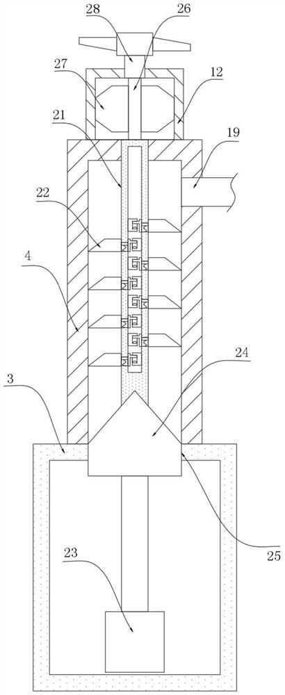
[0027] refer to Figure 1-5 , a chip liquid processing equipment for CNC machine tools, comprising a base 1, the upper end of the base 1 is fixed with a waste liquid pump 2, two impurity tanks 3, a cooling tank 5 and a recovery pump 6, and the upper ends of the two impurity tanks 3 are The purification box 4 is fixed, the two purification boxes 4 are connected with the waste liquid pump 2 and the cooling box 5 through the pipeline system, and the water inlet of the recovery pump 6 is fixed with a recovery pipe 7 that is communicated with the inside of the cooling box 5. There is a cooling and cooling mechanism, an impurity collection mechanism is arranged inside the impurity box 3, and an adsorption and impurity removal mechanism is arranged inside the purification box 4.

[0028] The pipeline system includes a liquid feeding pipe 18 connected to the water outlet of the waste liquid pump 2, the other end of the liquid feeding pipe 18 is connected with a "U"-shaped distribution...


PUM


Abstract

The invention discloses cutting fluid treatment equipment for a numerical control machine tool. The cutting fluid treatment equipment comprises a base, a waste liquid pump, two impurity boxes, a cooling box and a recovery pump are fixed at the upper end of the base, purification boxes are fixed at the upper ends of the two impurity boxes, the two purification boxes are connected with the waste liquid pump and the cooling box through a pipeline system, a recycling pipe communicating with the interior of the cooling box is fixed to a water inlet of the recycling pump, and a cooling mechanism is arranged in the cooling box. The cutting fluid treatment equipment has the advantages that cutting liquid can be concentrated in a concentration sleeve and transferred into a cooling pipe when passing through the cooling box, the cooling pipe is soaked in cooling liquid in the cooling box, heat of the cutting liquid can be absorbed by cooling liquid, the cutting liquid is sufficiently cooled, and the situation that normal work of equipment is affected due to the fact that the cutting liquid repeatedly works and the temperature is too high is avoided; and the absorbed heat can be quickly diffused to the outside through continuous flowing of the cooling liquid, so that continuous and effective cooling is realized.

Description

technical field [0001] The invention relates to the technical field of numerical control machine tool equipment, in particular to a chip liquid processing equipment for numerical control machine tools. Background technique [0002] CNC machine tools can better solve the problem of complex, precise, small batch, and multi-variety parts processing. It is a flexible and high-efficiency automatic machine tool, which represents the development direction of modern machine tool control technology chemical products. [0003] In the process of machining workpieces, CNC machine tools mainly use cutting fluid to cool the tool and the workpiece. During the cooling process, the cutting fluid will continuously take away the heat on the tool and the workpiece, and its own temperature will continue to rise. The liquid is cooled, and the iron scraps generated during the machining process will also be mixed with the chip liquid. Therefore, in order to realize the recycling and reuse of the c...

Claims


Application Information

Patent Timeline
IPC IPC(8): B23Q11/10B23Q11/00
CPCB23Q11/1069B23Q11/00
Inventor 刘秀福
Owner 刘秀福
Why Eureka
Try Eureka