

Polishing pad with grooves in surface
Patent Information
- Authority / Receiving Office
- CN · China
- Patent Type
- Applications(China)
- Current Assignee / Owner
- 广东粤港澳大湾区黄埔材料研究院
- Publication Date
- 2021-12-07
Smart Images
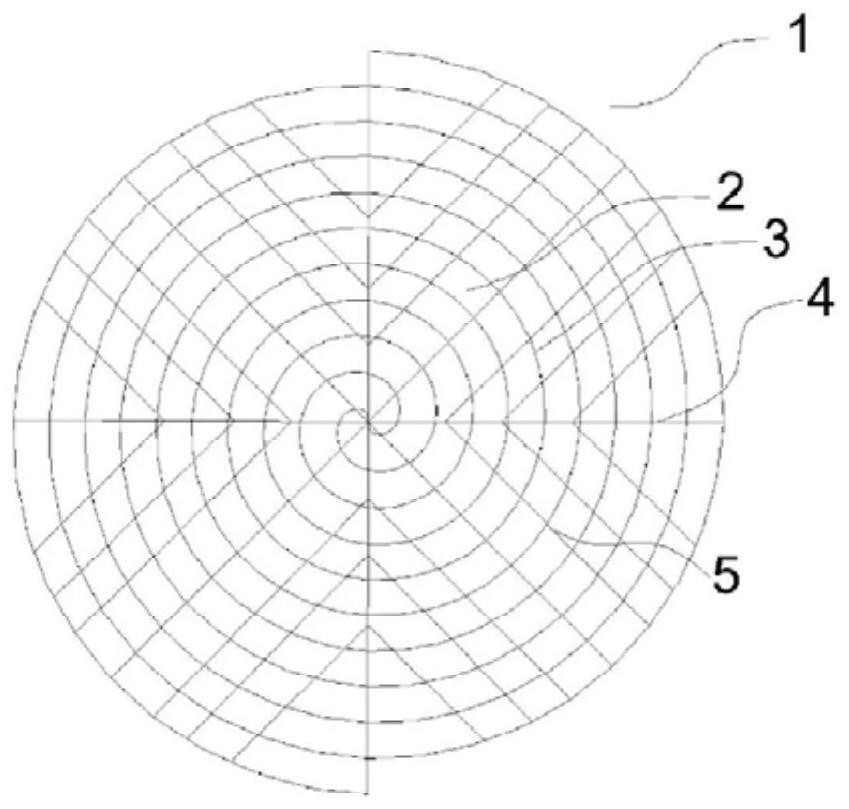
Figure 1 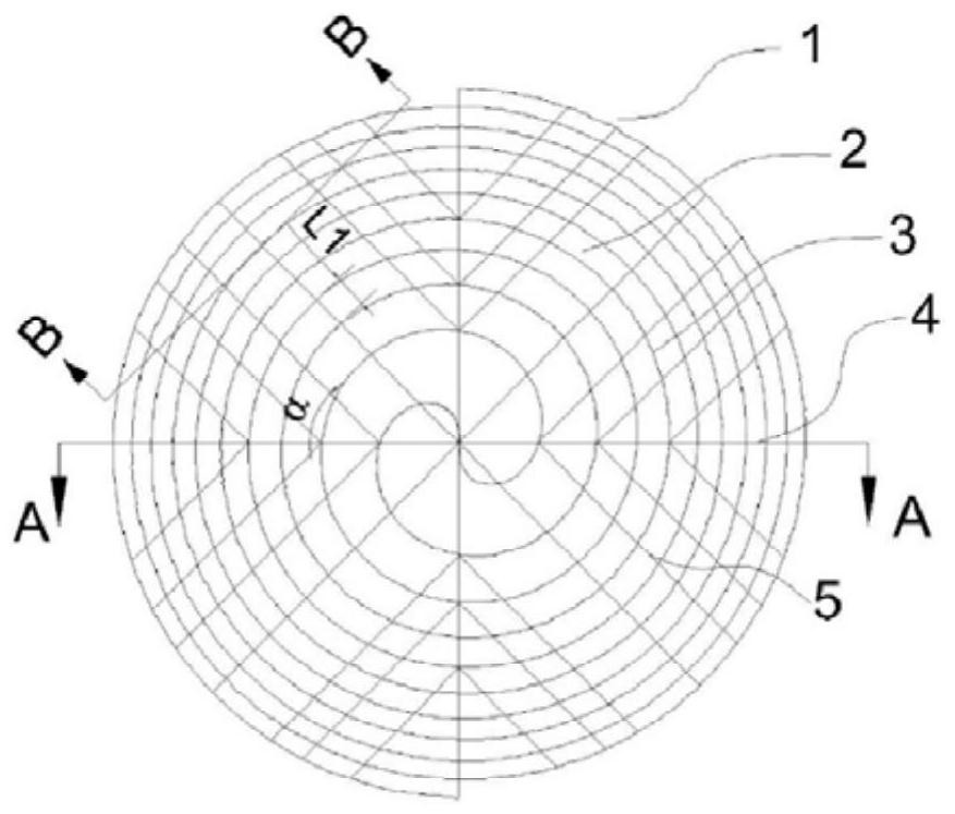
Figure 2 
Figure 3
Abstract
Description
technical field
[0001] The invention relates to the technical field of chemical mechanical polishing, in particular to a polishing pad with grooves on the surface. Background technique
[0002] With the development of the silicon integrated circuit technology industry, affected by the cost, the size of the silicon chip used increases, the integration of electronic components on it increases, and the feature size of the device is also continuously reduced. In order to ensure the quality of photolithography in the silicon wafer preparation process, the surface flatness of the silicon wafer is required to reach the nanometer level. Chemical mechanical polishing is currently the only method that can achieve global planarization of silicon wafers. The polishing pad is an important consumable in the chemical mechanical polishing process, which undertakes the functions of physical polishing and transportation of polishing fluid, and its quality directly affects the polishing effec...