Eureka AIR delivers breakthrough ideas for toughest innovation challenges, trusted by R&D personnel around the world.

Conventional layout helicopter and flight control method

A helicopter and layout technology, applied in the aviation field, can solve problems such as reducing aerodynamic efficiency, achieve high forward flight speed, and increase forward flight speed

Active Publication Date: 2021-12-07
NANJING UNIV OF AERONAUTICS & ASTRONAUTICS
View PDF7 Cites 0 Cited by
  • Summary
  • Abstract
  • Description
  • Claims
  • Application Information

AI Technical Summary

Problems solved by technology

In view of these two limitations, it has been proposed to use the ABC (forward blade concept) rotor to increase the maximum flight speed of the helicopter, but the ABC rotor generally adopts two counter-rotating coaxial rigidity due to the lift bias of the single rotor. Rotor, ABC single rotor, due to its structural characteristics, compared with the traditional single rotor when flying forward at high speed, avoids the disadvantage that the backward blade is more likely to enter the aerodynamic stall state due to waving, thereby reducing the aerodynamic efficiency, so that the forward blade can be better. It can exert its lift potential to provide greater power for the forward flight of the helicopter. If the helicopter with the conventional layout can apply the ABC single rotor while overcoming the characteristics of its lift bias, the maximum forward flight speed of the helicopter with the conventional layout can be increased.

Method used


Image

  • Conventional layout helicopter and flight control method
  • Conventional layout helicopter and flight control method
  • Conventional layout helicopter and flight control method

Examples


Embodiment 2

[0045] The present embodiment provides a flight control method of a conventional layout helicopter 100, comprising the following steps:

[0046] S1. Obtain the current rolling moment Mb and the maximum rolling moment M of the short wings of the conventional layout helicopter 100 bmax , Minimum rolling moment M bmin and the current roll moment M of the ABC single rotor 8 r ;

[0047] S2. Judging the current rolling moment M of the ABC single rotor 8 r The current roll moment M with the short wing b , the maximum rolling moment M bmax , Minimum rolling moment M bmin size relationship;

[0048] S31. When the current rolling moment M of the ABC single rotor 8 r Greater than the maximum rolling moment M of the short wing bmax , obtain the rolling moment that needs to be reduced by the ABC single-rotor 8, expand the frame assembly 9 to the maximum and reduce the rolling moment of the ABC single-rotor 8 to the target value, specifically, the target value is the maximum rollin...


PUM


Abstract

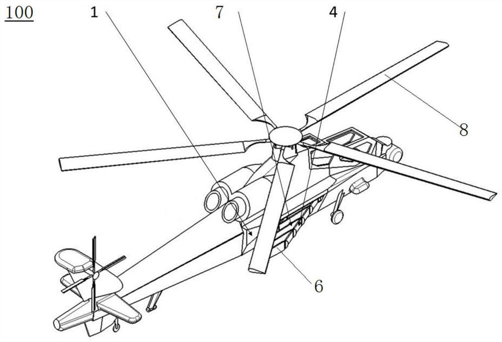
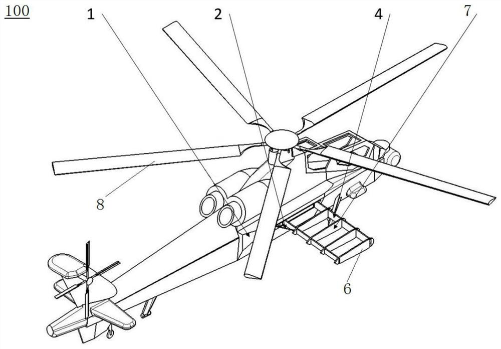
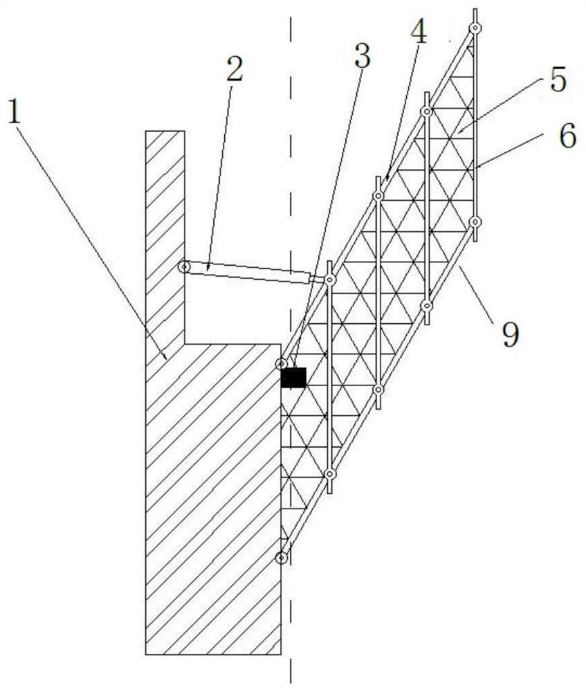
The invention discloses a conventional layout helicopter and a flight control method, and relates to the technical field of aviation. The conventional layout helicopter comprises a machine body, an ABC single rotor and a stub wing, the machine body comprises a fuselage and a driving mechanism, and the driving mechanism is arranged in the fuselage; the ABC single rotor is arranged at the top of the fuselage and fixedly connected to the output end of the driving mechanism, and the driving mechanism can change the rolling torque of the ABC single rotor; and the stub wing is arranged on the fuselage on one side of a backward side paddle of the ABC single rotor, the stub wing comprises a driving element, a frame assembly and a skin, the frame assembly is movably connected to the fuselage, one end of the driving element is connected to the fuselage, the other end of the driving element is connected to the frame assembly, the driving element can drive the frame assembly to do reciprocating motion in the forward flight direction of the helicopter, the area of the frame assembly changes in the reciprocating motion process, and the frame assembly is wrapped with the skin. According to the conventional layout helicopter provided by the invention, the maximum forward flight speed of a traditional conventional layout helicopter can be improved.

Description

technical field [0001] The invention relates to the field of aviation technology, in particular to a conventional layout helicopter and a flight control method. Background technique [0002] Due to its high hovering efficiency, helicopters have unique application value in many aspects, but compared with airplanes, helicopters have a shortcoming in their forward flight speed. [0003] A conventional layout helicopter refers to a helicopter with a single rotor and a tail rotor configuration. The lift of the vertical flight and the forward power of the helicopter are provided by the rotation of the single rotor. The single rotor with pitch-variable hinges and shimmy hinges, the separation of the forward blade shock wave and the rearward blade side airflow are important reasons for limiting the maximum flight speed of conventional layout helicopters. In view of these two limitations, it has been proposed to use the ABC (forward blade concept) rotor to increase the maximum fligh...

Claims


Application Information

Patent Timeline
IPC IPC(8): B64C27/22B64C27/32B64C27/12B64C3/38B64C3/56B64C1/06B64C1/12
CPCB64C27/22B64C27/32B64C27/12B64C3/38B64C3/56B64C1/068B64C1/12Y02T50/40
Inventor 赵国庆崔壮壮招启军王博周旭丁岩
Owner NANJING UNIV OF AERONAUTICS & ASTRONAUTICS
Why Eureka
Eureka Blog
Learn More