Leveler with residual coal collection mechanism

A collection mechanism and coal leveling device technology, applied in the direction of conveyors, conveyor objects, conveyor control devices, etc., can solve the problems of difficult coal collection in the collection tank, inevitable coal waste, fixed volume of the collection tank, etc.

Active Publication Date: 2022-05-03
HUAIBEI MINING IND
View PDF10 Cites 0 Cited by
  • Summary
  • Abstract
  • Description
  • Claims
  • Application Information

AI Technical Summary

Problems solved by technology

[0005] When the coal leveler pushes the raised coal material in the train carriage, the raised coal material on both sides will slide down along the side positions, and the raised coal material at the middle position will easily move from the train carriage in the opposite direction after being pushed. One side slips, and the collecting troughs located on both sides of the train car are difficult to collect, which inevitably wastes coal, and the volume of the collecting trough is fixed, and it is difficult to continue to collect coal after the overflowing collecting trough

Method used


Image

  • Leveler with residual coal collection mechanism
  • Leveler with residual coal collection mechanism
  • Leveler with residual coal collection mechanism

Examples


Embodiment 1

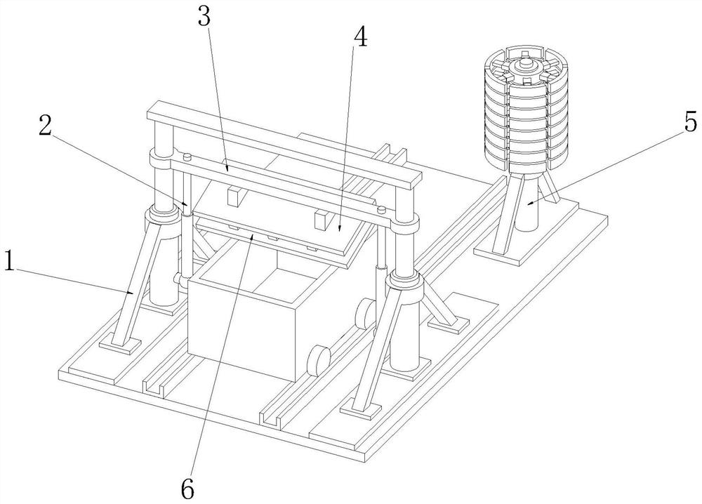
[0041] see Figure 1-4 As shown, the coal flatter with residual coal collection mechanism includes a bracket 1, a lifting rod 2, a support plate 3 and a flat coal plate 4, the inner wall of the bracket 1 is connected with the lifting rod 2, and the upper side wall of the lifting rod 2 is connected with the supporting plate 3 , a flat coal plate 4 is connected to the middle position of the lower surface of the support plate 3;

[0042] The lifting rod 2 connected to the support 1 can adjust the height of the support plate 3 under the control of the control equipment after the infrared detection equipment of the leveler detects the height of the train carriage, so that the leveling coal connected to the lower surface of the support plate 3 Plate 4 can carry out level coal operation to the passing train carriage;

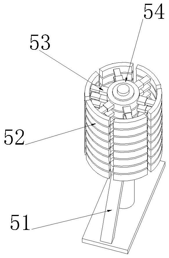
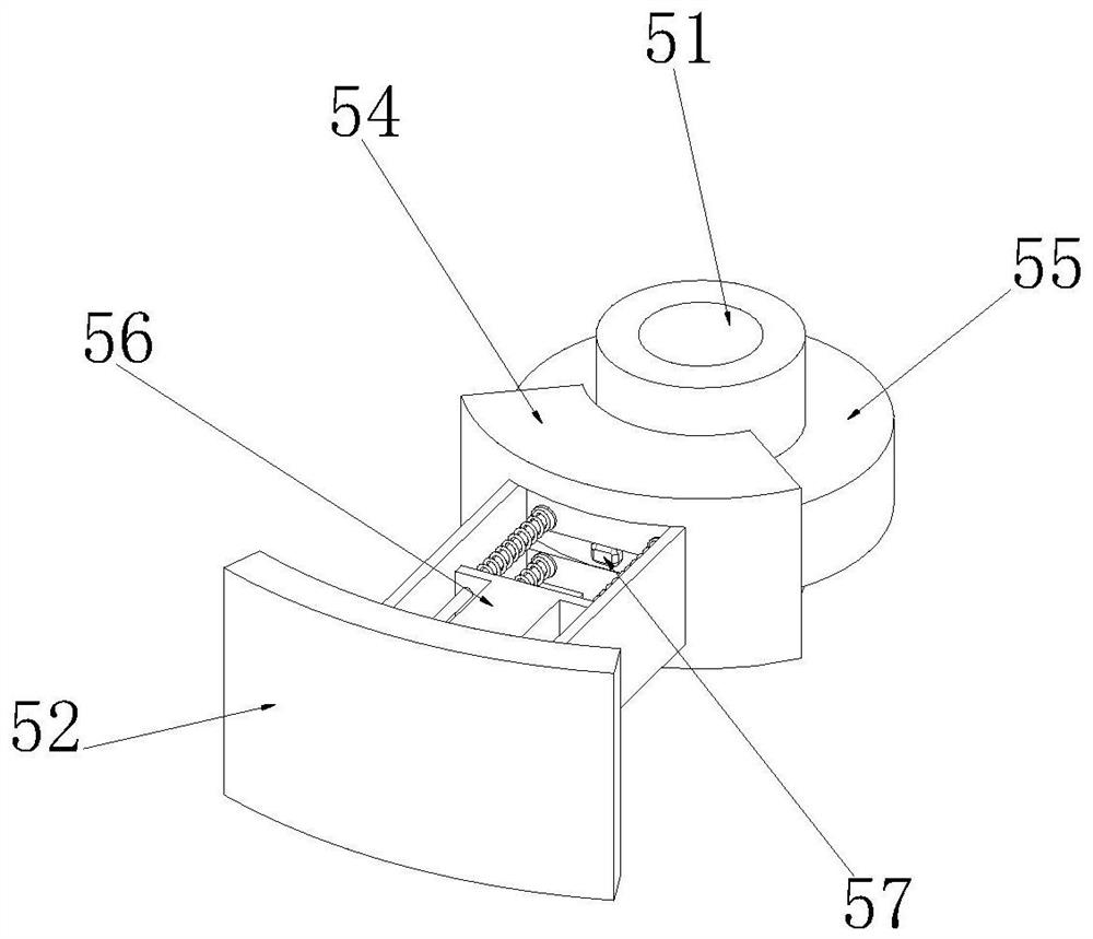
[0043] One side behind the support 1 is provided with a height-measuring mechanism 5, the height-measuring mechanism 5 includes a support frame 51, and several evenly...

Embodiment 2

[0046] When the leveling coal plate 4 is performing the operation of leveling the coal in the train carriage, the coal that is positioned on both sides of the train carriage and is higher than the train carriage is easy to slide down from the side of the train carriage under the flat push of the leveling coal plate 4, and is located in the middle of the train carriage. The coal that is higher than the train compartment at the position is easy to slide down from the opposite direction position of the train compartment under the flat push of the flat coal plate 4, causing the loss of coal resources;

[0047] see Figure 5-7 As shown, the lower surface of the flat coal plate 4 is provided with a collection mechanism 6, the collection mechanism 6 includes an adjustment plate 62, and one end of the adjustment plate 62 is integrally formed with an extrusion plate 61, and the inclined extrusion plate 61 can squeeze each other after contacting the train carriage. pressure, so that the...

Embodiment 3

[0050] The coal loaded in the train car is unevenly distributed, so that after the flat coal plate 4 performs the coal leveling operation on the train car, part of the coal falls from both sides of the train car, and the middle concave position cannot be supplemented with coal. The coal loaded in the train car amount reduced;

[0051] see Figure 8-9 As shown, a coal return mechanism 7 is provided on both sides of the lower surface of the coal collection box 63, and the coal return mechanism 7 includes a blanking box 72, and a drive motor 73 is connected to one side of the outer wall of the blanking box 72, and a drive motor 73 is connected to the lower surface of the blanking box 72. Return pipe 74, the inner side wall of return pipe 74 is rotatably connected with shaftless auger 75, the outer side wall of blanking box 72 is connected with transmission box at the position corresponding to driving motor 73, and the rotating shaft on the output end of driving motor 73 inside th...


PUM


Abstract

The invention relates to the technology of a coal leveler, which is used to solve the problem that the coal material slips to the outside of the train compartment when the coal leveler performs coal leveling operations on the coal accumulated on the train carriage, and is specifically a coal leveler with a residual coal collection mechanism , including a bracket, a lifting rod, a support plate and a flat coal plate, the inner wall of the support is connected with a lifting rod, the upper side wall of the lifting rod is connected with a support plate, and the middle position of the lower surface of the support plate is connected with a flat coal plate, One side behind the support is provided with a height-measuring mechanism, and the height-measuring mechanism includes a support frame; the present invention evenly disperses the coal materials on the train carriages through two rows of bulk boards, and uses the baffle plates on both sides to The coal material that is easy to slide on the side is blocked, so that the coal material is piled up on the top of the train car, and the coal material that is still higher than the train car after being evenly distributed is collected inside the coal collection box, and there is no shaft auger in the return pipe. Under the action, the transmission falls back to the interior of the subsequent train compartment to supplement the coal in the compartment.

Description

technical field [0001] The invention relates to the technology of a coal leveler, in particular to a leveler with a residual coal collection mechanism. Background technique [0002] During the loading process of coal, because the coal outlet of the coal bunker directly loads the coal into the vehicle compartment, many uneven hills will be formed inside the compartment, which does not meet the transportation requirements. Therefore, the compartment must be inspected before transportation. The surface of the internal coal material is leveled, that is, the raised part is filled to the missing position, so as to avoid the occurrence of coal material scattering during transportation. [0003] The patent with the application number CN201921096873.1 is specifically a coal leveling device with a coal slag collection function and a good levelling effect. The coal material that falls from the side is collected to reduce the waste of coal material; [0004] The technical problem that...

Claims


Application Information

Patent Timeline
Patent Type & Authority Patents(China)
IPC IPC(8): B65G69/04B65G67/04B65G43/00
CPCB65G69/04B65G67/04B65G43/00B65G2201/045
Inventor 周宗丰刘锋陈坤杨永锋欧战备
Owner HUAIBEI MINING IND
Why Eureka
Try Eureka