Bracket structure for chute area of dry quenching furnace

A technology for CDQ coke oven and chute area, which is applied in coke oven, coke cooling, petroleum industry, etc., can solve the problem of cracking of chute partition walls, prolong service life, improve masonry quality, and improve use efficiency Effect

Pending Publication Date: 2021-12-07
ACRE COKING & REFRACTORY ENG CONSULTING CORP DALIAN MCC
6 Cites 0 Cited by

AI-Extracted Technical Summary

Problems solved by technology

[0005] The invention provides a corbel structure in the chute area of ​​a CDQ coke oven. By placing support members in the refractory mud joints between the corbel brick layers, it can effectively prevent the deformation ...

Abstract

The invention relates to a bracket structure for a chute area of a dry quenching furnace. The bracket structure is formed by building a plurality of layers of bracket bricks; and a plurality of supporting pieces are arranged between every two adjacent layers of bracket bricks, the supporting pieces are hard supporting pieces, the thickness of the supporting pieces is the same as that of mortar joints, the top faces of the supporting pieces make direct contact with the upper layer of bracket bricks, and the bottom faces of the supporting pieces make direct contact with the lower layer of bracket bricks. The supporting pieces are placed in the refractory mortar joints between the bracket brick layers, so that the problems of sinking of the annular air duct and cracking of the chute partition wall caused by deformation of the bracket mortar joints and inaccurate bracket elevation control are effectively prevented, the masonry quality of the dry quenching furnace is improved, and the service life of the dry quenching furnace is prolonged.

Application Domain

Coke quenching

Technology Topic

Mortar jointStructural engineering +2

Image

  • Bracket structure for chute area of dry quenching furnace
  • Bracket structure for chute area of dry quenching furnace
  • Bracket structure for chute area of dry quenching furnace

Examples

  • Experimental program(1)

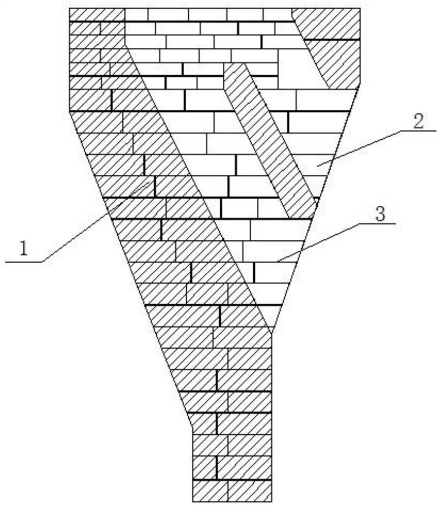
Example Embodiment

[0020] The specific embodiments of the present invention will be further described below in conjunction with the accompanying drawings:
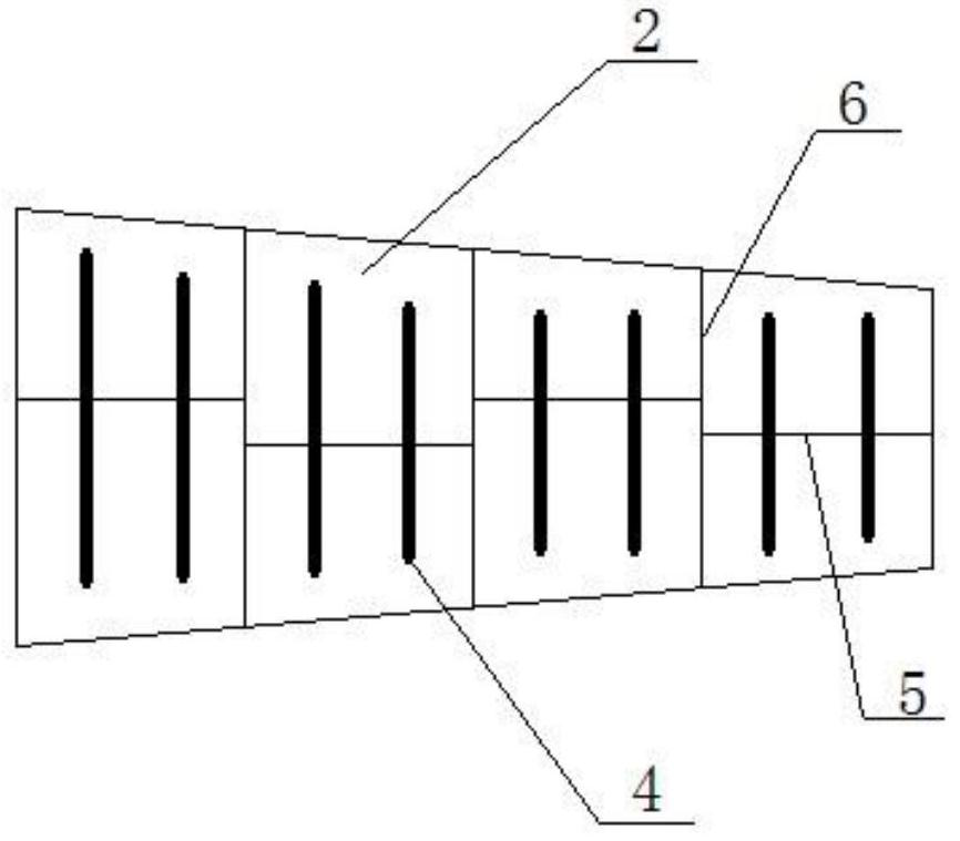
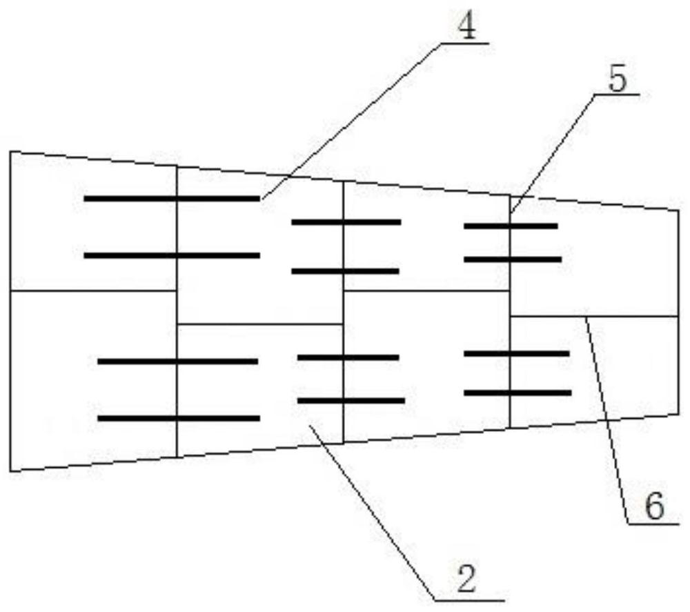
[0021] like figure 1 As shown in the figure, the present invention is a corbel structure in the chute area of ​​the CDQ, and the corbel structure is made of multi-layer corbel bricks 2; such as Figure 2-Figure 4 As shown, there are several supports 4 between adjacent 2-layer corbel bricks 2, the support 4 is a hard support, and its thickness is the same as the thickness of the ash joint 3, and the top surface of the support 4 is the same as the upper corbel brick. Direct contact, the bottom surface of the support 4 is in direct contact with the lower corbel brick.
[0022] The thickness of the support member 4 is 2-5mm, and is divided into various specifications according to the thickness, and the support member 4 of the corresponding thickness is selected according to the elevation of different corbel brick layers.
[0023] The support member 4 is a strip-shaped support member or a plate-shaped support member, and at least two support members 4 are arranged on the same corbel brick 2; wherein the strip-shaped support members are arranged at intervals, and the same strip-shaped support member spans adjacent to each other in the horizontal or vertical direction. 2 corbel bricks 2 (such as figure 2 , image 3 shown); the plate-like supports are evenly spaced on the same corbel brick 2 (such as Figure 4 shown).
[0024] The outline of the plate-shaped support is circular or polygonal.
[0025] Except for the brick seam 5 at the span, the distance between the support 4 and the other brick seams 6 or the edge of the corbel brick 2 is at least 20mm, that is, the support 4 is embedded in the ash seam 3.
[0026] The support member 4 is made of heat-resistant stainless steel or hard refractory material.
[0027] like figure 1 As shown, the corbel structure of CDQ oven chute area 1 is composed of multi-layer corbel bricks 2, and the corbel bricks 2 are made of refractory mud to form ash joints 3 during masonry. In the present invention, during the masonry process of the corbel, a hard support 4 is placed in the ash joint 3 between the corbel brick layers. The thickness of the support 4 is the same as the thickness of the ash joint 3. The support 4 in the middle is hard contact to ensure that the ash seam 3 will not be deformed under the support of the support 4 .
[0028] Preferably, two supports 4 are placed on each corbel brick 2 at least at a distance to ensure the stability and flatness of the corbel brick layer and prevent the corbel brick 2 from tilting due to single-point or unilateral support.
[0029] The thickness of the support member 4 is divided into several specifications, preferably four specifications of 2mm, 3mm, 4mm and 5mm. Each corbel brick layer selects the required thickness of the support member 4 according to its elevation, and realizes the thickness of the ash joint 3. precise adjustment. When the elevation of the corbel is inconsistent due to the deviation of the size of the corbel brick 2 or the elevation of the process shell, the support member 4 with different thicknesses can be used to assist in adjusting the height of the ash joint 3 to avoid the occurrence of ash due to the high fluidity of the mortar. The problem of deformation of seam 3 and difficult control of the height of the corbel.
[0030] The support 4 should be completely embedded in the ash gap 3 and at least 20mm away from the edge of the ash gap 3 to prevent voids in the ash gap 3 caused by the erosion of the support 4 by the high temperature airflow during the hot production of the CDQ coke oven.
[0031] The support member 4 can be a strip-shaped support member, and the strip-shaped support member can be placed longitudinally or laterally (such as figure 2 , image 3 shown). The supporting member 4 can also be a circular or other shaped plate-shaped supporting member, such as Figure 4 shown.
[0032] The support 4 can be made of heat-resistant metal materials such as heat-resistant stainless steel, or can be made of hard refractory materials such as ceramic refractory materials. It is required to have a certain cold compressive strength, but its corrosion resistance requirements are not. High, because the support 4 is wrapped in the ash joint 3, it only needs to play a supporting role in the cold state; after the refractory mud solidifies, the ash joint 3 itself can play a supporting role.

PUM

no PUM

Description & Claims & Application Information

We can also present the details of the Description, Claims and Application information to help users get a comprehensive understanding of the technical details of the patent, such as background art, summary of invention, brief description of drawings, description of embodiments, and other original content. On the other hand, users can also determine the specific scope of protection of the technology through the list of claims; as well as understand the changes in the life cycle of the technology with the presentation of the patent timeline. Login to view more.

Similar technology patents

Punching positioning device

InactiveCN103394731AThe punching position is accurateExtended service life
Owner:STATE GRID CORP OF CHINA +1

Masonry engineering construction device and construction process

ActiveCN112227749AImprove masonry quality
Owner:飞帆集团有限公司

Method for preparing abrasion-resistant super-hydrophobic ceramic coating through thermal spraying technology and product

ActiveCN105316619AExtended service lifegood self-cleaning
Owner:NINGBO INST OF MATERIALS TECH & ENG CHINESE ACADEMY OF SCI

Classification and recommendation of technical efficacy words

  • Extended service life
  • Improve masonry quality

Fracturing manifold quick connecting device

Owner:YANTAI JEREH PETROLEUM EQUIP & TECH

Modified asphalt composition with creeping characteristic and preparation method thereof

InactiveCN102020859Aavoid rapid agingExtended service life
Owner:ZHEJIANG WOPUMAN HIGH NEW MATERIALS

Masonry engineering construction device and construction process

ActiveCN112227749AImprove masonry quality
Owner:飞帆集团有限公司
Why Eureka
Try Eureka