Movable scaffold
A scaffolding and erecting technology, which is applied to the accessories of scaffolding, housing structure support, housing structure support and other directions, can solve the problems of difficult to guarantee construction safety, affect construction efficiency, and inconvenient construction, and achieve improved construction efficiency, construction safety, convenience and convenience. effect of placement
- Summary
- Abstract
- Description
- Claims
- Application Information
AI Technical Summary
Problems solved by technology
Method used
Image
Examples
Embodiment 1
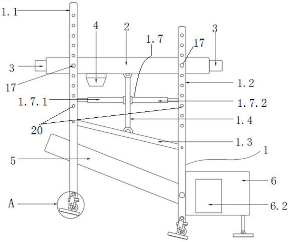
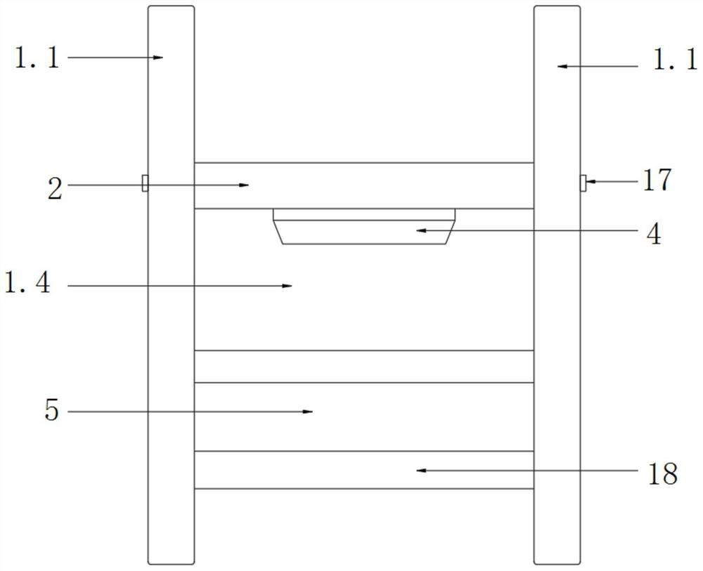
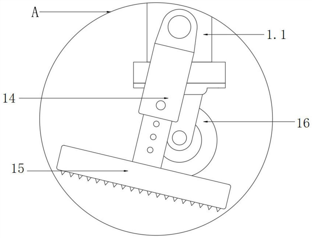
[0057] Such as figure 1 , figure 2 The mobile scaffold shown includes a frame body 1, a platform 2, fasteners, a balance support assembly, a mobile locking structure, an unloading mechanism and a buffer anti-skid device.
[0058] Wherein, the frame body 1 includes a first stand 1.1, a second stand 1.2 and connecting pieces. The first stand 1.1 and the second stand 1.2 are arranged at intervals in the first direction, that is, in the horizontal direction. The connecting piece is arranged between the first stand 1.1 and the second stand 1.2 and is hingedly connected with the first stand and the second stand respectively. The connecting piece in this embodiment is preferably a connecting rod 1.3. One end of the connecting rod 1.3 is hinged with the first stand 1.1, and the other end of the connecting rod 1.3 is hinged with the second stand 1.2.
[0059] The platform 2 is kept horizontal or nearly horizontal, and the platform 2 is detachably connected with the first stand 1.1 a...
Embodiment 2
[0083] Such as Figure 7 The mobile scaffold shown is roughly the same as the structure of embodiment 1, the difference is:
[0084] The connecting piece in this embodiment includes a connecting rod 1.3 and a connecting support rod 1.5. One end of the connecting rod 1.3 is hinged with the first stand 1.1, and the other end of the connecting rod 1.3 is hinged with the second stand 1.2. The lower end of the connecting support rod 1.5 is fixedly connected with the connecting rod 1.3, and the upper end of the connecting supporting rod 1.5 is provided with a horizontal rotating shaft 1.6 and is rotationally connected with the platform 2 through the rotating shaft 1.6. The axis of rotation of the rotating shaft 1.6 is perpendicular to and intersects with the center of gravity of the platform 2 . In this embodiment, the rotation axis of the rotating shaft 1.6 is parallel to the first stand 1.1 and the second stand 1.2. By restricting the position of the axis of rotation of the pla...
Embodiment 3
[0086] Such as Figure 8 The mobile scaffold shown is roughly the same as the structure of embodiment 2, the difference is:
[0087] The platform 2 of this embodiment is rotatably connected with the second stand 1.2 through a bolt 17 . The center line of the socket 20 on the second stand 1.2 is perpendicular to and intersects with the center of gravity line of the platform 2 . Therefore, when the platform 2 is only connected to the two jacks 20 on the second stand 1.2 through the two bolts 17, the platform 2 can maintain a horizontal state, and the frame body 1 can move on the slope ground. When the platform 2 needs to be fixed, the additional bolt 17 is matched with the socket 20 on the first stand 1.1 and inserted into the installation hole of the platform 2. The balance support assembly in this embodiment not only includes the counterweight 3, but also includes the bolt 17 that cooperates with the second stand 1.2. Similarly, the platform 2 can also be rotatably connecte...
PUM
 Abstract
Description
Claims
Application Information
 - R&D
- Intellectual Property
- Life Sciences
- Materials
- Tech Scout
- Unparalleled Data Quality
- Higher Quality Content
- 60% Fewer Hallucinations
Browse by: Latest US Patents, China's latest patents, Technical Efficacy Thesaurus, Application Domain, Technology Topic, Popular Technical Reports.
© 2025 PatSnap. All rights reserved.Legal|Privacy policy|Modern Slavery Act Transparency Statement|Sitemap|About US| Contact US: help@patsnap.com


