Heavy four-column pull rod air cylinder

A pull rod, heavy-duty technology, applied in the direction of fluid pressure actuation device, etc., can solve the problems of unstable transmission, small metal contact area, small friction and power loss, etc., to solve the problem of unstable transmission, avoid accumulation of oil stains, and solve oil corrosion Effect

Pending Publication Date: 2021-12-07
JIANGSU SHENSHIDA PNEUMATIC TECH CO LTD
View PDF1 Cites 0 Cited by
  • Summary
  • Abstract
  • Description
  • Claims
  • Application Information

AI Technical Summary

Problems solved by technology

[0005] But above-mentioned technical scheme still has many shortcomings when practical application;
[0006] 1. When improving the tie-rod cylinder in the comparison document, the tie-rod and the piston are used to realize the movement guidance, the metal contact area is small, the friction force is small, the power loss is small, and the whole cylinder has the advantages of stable operation, although this can make it drive The efficiency is high, but when the rod and the piston are in operation, the cylinder itself will vibrate, and the continuous operation of the cylinder will cause the rod to vibrate, thereby increasing the friction between the two, resulting in unstable transmission;
[0007] 2. Since the comparison document is to set the tie rod inside the cylinder and isolate it from the air, it is especially suitable for corrosive environment conditions. Although this can prevent the tie rod from being corroded in a corrosive environment, it will be used when the cylinder is working. The oil used in the cylinder is brought into the cylinder and adheres to the inner wall of the cylinder. After a long period of accumulation, it will cause the oil to drop on the tie rod, causing corrosion, etc.

Method used


Image

  • Heavy four-column pull rod air cylinder
  • Heavy four-column pull rod air cylinder
  • Heavy four-column pull rod air cylinder

Examples


Embodiment Construction

[0026] The following will clearly and completely describe the technical solutions in the embodiments of the present invention with reference to the accompanying drawings in the embodiments of the present invention. Obviously, the described embodiments are only some, not all, embodiments of the present invention. Based on the embodiments of the present invention, all other embodiments obtained by persons of ordinary skill in the art without making creative efforts belong to the protection scope of the present invention.

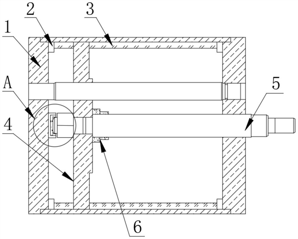
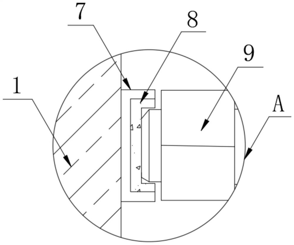
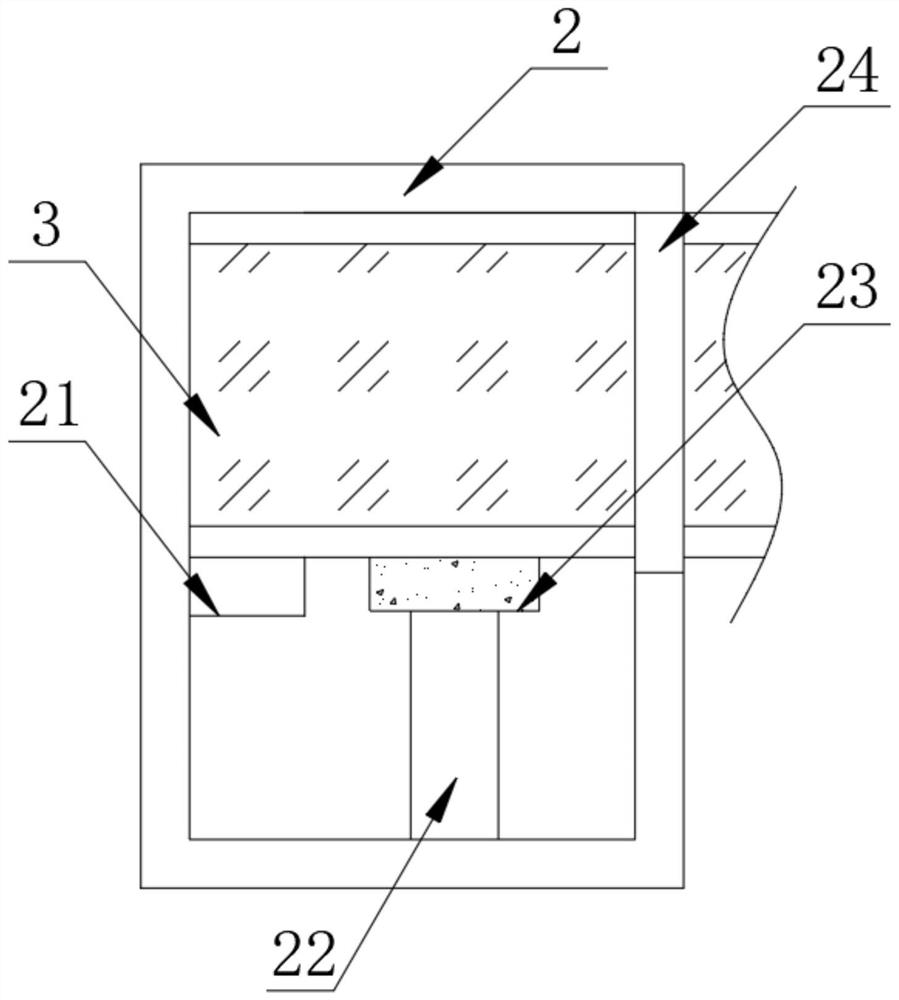
[0027] as attached Figure 1-4 The heavy-duty four-column tie-rod cylinder shown includes a cylinder 1, a piston 4 and a tie rod 5. A fixed block 2 is fixedly installed on the left and right sides of the upper and lower sides of the inner cavity of the cylinder 1, and the other side of the fixed block 2 is fixedly connected with an adsorption top plate. 3. The upper and lower sides of one side of the piston 4 are fixedly fitted with a buffer splint 6, one side...


PUM


Abstract

The heavy four-column pull rod air cylinder comprises a cylinder barrel, a piston and a pull rod, fixing blocks are fixedly installed on the left side and the right side of the upper face and the lower face of an inner cavity of the cylinder barrel, the other side of each fixing block is fixedly connected with an adsorption top plate, and the upper face and the lower face of one side of the piston are fixedly sleeved with buffering clamping plates. A clamping base is welded to one side of the cylinder barrel, the other side of the clamping base is fixedly sleeved with a buffering clamping plate, and a nut is connected to the other side of the buffering clamping plate in a clamped mode. By arranging the clamping buffer device, when the pull rod and the piston operate, the air cylinder vibrates, the pull rod vibrates under the continuous work of the air cylinder, at the moment, the clamping buffer device automatically buffers and protects the pull rod when the air cylinder works, the problem that friction force is increased due to vibration of the pull rod is solved, and the service life of the pull rod is prolonged. And the problem of unstable transmission is solved, so that the transmission stability of the pull rod is ensured.

Description

technical field [0001] The invention relates to the technical field of tie rod cylinder equipment, more specifically, the invention is a heavy-duty four-column tie rod cylinder. Background technique [0002] At present, in the existing cylinder, a piston is installed in the cylinder, a piston rod is installed in the middle of the piston, end caps are arranged at both ends of the cylinder, and two or more pull rods are evenly arranged in the outer circumferential direction of the cylinder, passing through the end cap, Both ends are tightened with nuts, and the piston rod passes through the end cover to realize connection with other mechanisms. [0003] When the existing cylinder works, the cylinder and the piston, the piston rod and the end cover are guided together, the metal contact surface is large, the friction force is large, the power loss is large, and the cylinder heats up significantly during frequent work; the tie rod is arranged on the outer periphery of the cylind...

Claims


Application Information

Patent Timeline
Patent Type & Authority Applications(China)
IPC IPC(8): F15B15/14F15B15/20F15B15/22
CPCF15B15/14F15B15/20F15B15/226
Inventor 黄奔望
Owner JIANGSU SHENSHIDA PNEUMATIC TECH CO LTD
Why Eureka
Try Eureka