Electronic thermostatic valve, control method of electronic thermostatic valve and water heater

A technology of electronic constant temperature and control method, which is applied in solar collector controllers, fluid heaters, solar collectors, etc., to achieve accurate water temperature and improve accuracy

Active Publication Date: 2021-12-07
WUHU MIDEA KITCHEN & BATH APPLIANCES MFG CO LTD +1
View PDF5 Cites 0 Cited by
  • Summary
  • Abstract
  • Description
  • Claims
  • Application Information

AI Technical Summary

Problems solved by technology

[0003] The embodiment of the present application provides an electronic thermostatic valve, its control method and water heater, so as to solve or alleviate one or more technical problems in the prior art

Method used


Image

  • Electronic thermostatic valve, control method of electronic thermostatic valve and water heater
  • Electronic thermostatic valve, control method of electronic thermostatic valve and water heater
  • Electronic thermostatic valve, control method of electronic thermostatic valve and water heater

Examples


Embodiment 1

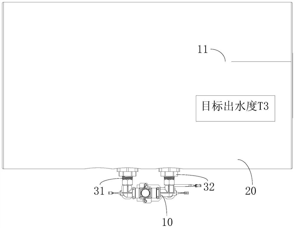
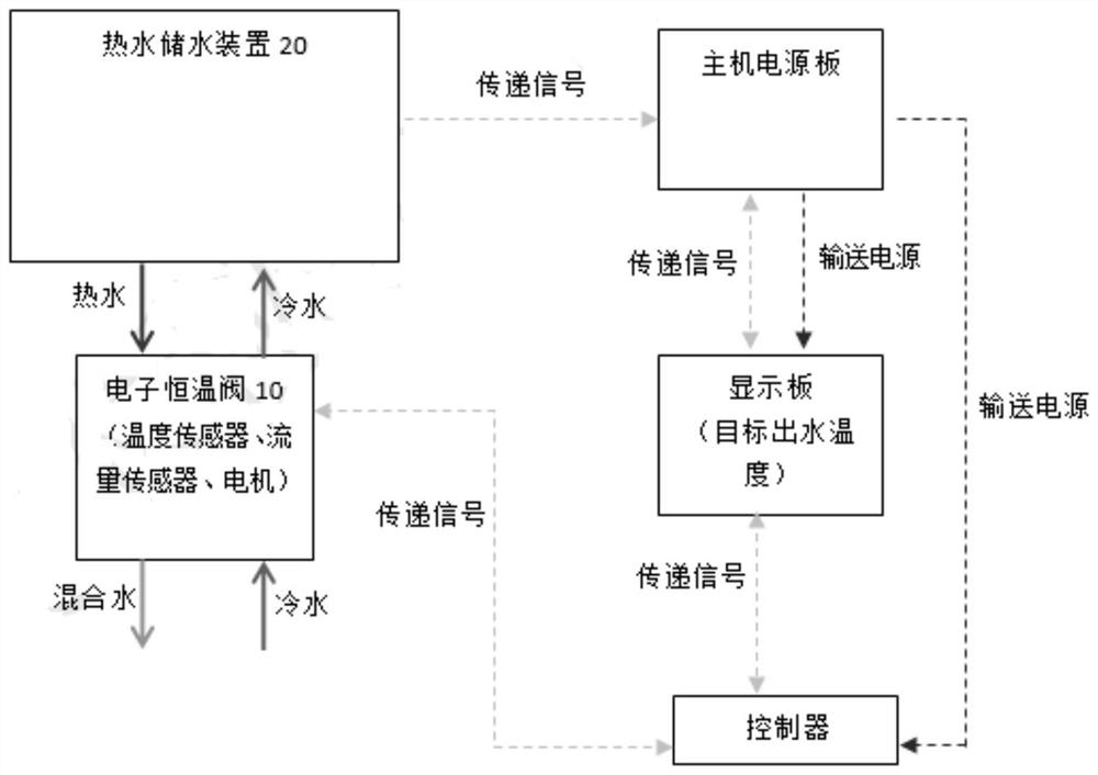
[0027] figure 1 A partial structural schematic diagram of a water heater according to an embodiment of the present application is shown. Such as figure 1 As shown, the water heater includes an electronic thermostatic valve 10 and a hot water storage device 20 . Wherein, the electronic thermostatic valve 10 is arranged outside the hot water storage device 20 . In this embodiment, the water heater may be an electric water heater, a solar water heater or a heat pump, etc., which is not limited in this embodiment, but is preferably a water heater with a hot water storage device.

[0028] The electronic thermostatic valve 10 has a hot water inlet (not shown in the figure), and the hot water inlet is connected with the hot water storage device 20, so that the hot water in the hot water storage device 20 can enter the electronic thermostat through the hot water inlet. In the mixing chamber of valve 10. Such as figure 1 As shown, the hot water inlet communicates with the hot wate...

Embodiment 2

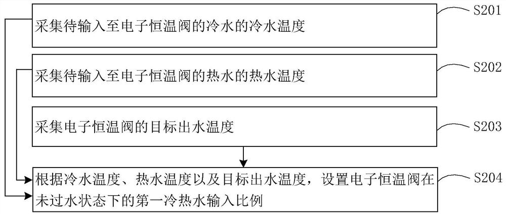
[0050] The difference between the second embodiment and the first embodiment lies in the different setting methods of the input ratio of the cold and hot water of the electronic thermostatic valve 10 in the non-passing state. For the convenience of description, in the second embodiment, the cold and hot water input ratio of the electronic thermostatic valve 10 in the non-passing state is the second cold and hot water input ratio.

[0051] Specifically, the method of the embodiment of the present application includes: detecting the duration of the electronic thermostatic valve in the non-water-passing state; and setting the second cold and hot water input ratio of the electronic thermostatic valve in the non-water-passing state according to the duration.

[0052] When the water heater is in normal use and the water is turned off at the end of the user, part of the hot water in the outlet pipe of the water heater cannot be discharged. At this time, the water heater is in normal u...


PUM


Abstract

The embodiment of the invention provides an electronic thermostatic valve, a control method of the electronic thermostatic valve and a water heater. The control method comprises the steps that the cold water temperature of cold water to be input into the electronic thermostatic valve is collected; the hot water temperature of hot water to be input into the electronic thermostatic valve is collected; the target water outlet temperature of the electronic thermostatic valve is collected; and according to the cold water temperature, the hot water temperature and the target outlet water temperature, the first cold and hot water input proportion of the electronic thermostatic valve in the non-water-passing state is set. According to the control method, the first cold and hot water input proportion of the electronic thermostatic valve when the water heater is in a standby state is determined by collecting the numerical values of the hot water temperature T1 and the cold water temperature T2 and the target outlet water temperature T3, the accuracy of the standby opening degree of the electronic thermostatic valve can be improved, and the more accurate outlet water temperature can be achieved.

Description

technical field [0001] The present application relates to the technical field of water heaters, in particular to an electronic thermostatic valve, a control method thereof, and a water heater. Background technique [0002] At present, most of the thermostatic valves used in the market are external mechanical thermostatic valves. Mechanical thermostatic valves have a long response time to temperature adjustment, and the accuracy of temperature adjustment is not high. They belong to the category of fuzzy temperature control. Even electronic thermostatic valves are mostly external, and there are problems such as inaccurate opening judgment value and long temperature adjustment time when used for the first time. Contents of the invention [0003] Embodiments of the present application provide an electronic thermostatic valve, its control method, and a water heater, so as to solve or alleviate one or more technical problems in the prior art. [0004] In the first aspect, the e...

Claims


Application Information

Patent Timeline
Patent Type & Authority Applications(China)
IPC IPC(8): F24H9/20F24S50/40F16K37/00
CPCF24H9/2007F24H9/2021F24S50/40F16K37/005Y02E10/40
Inventor 卢淑霞
Owner WUHU MIDEA KITCHEN & BATH APPLIANCES MFG CO LTD
Why Eureka
Try Eureka