Lithium battery cell pole piece crushing and separating equipment
A technology for separating equipment and lithium batteries, applied in battery recycling, recycling technology, recycling by waste collectors, etc., can solve the problems of reduced recycling quality, spilled on the ground, danger, etc., to increase traction area, increase stability, The effect of preventing loss due to breakage
- Summary
- Abstract
- Description
- Claims
- Application Information
AI Technical Summary
Problems solved by technology
Method used
Image
Examples
Embodiment 1
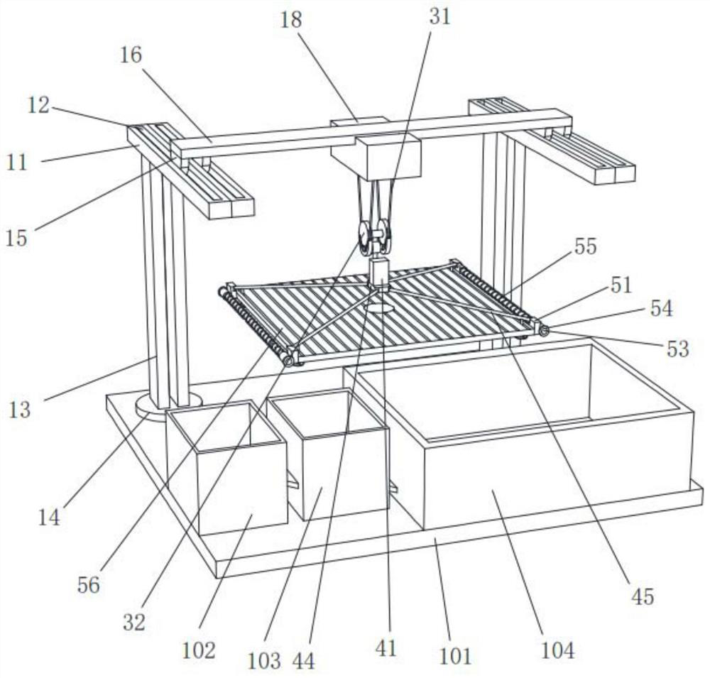
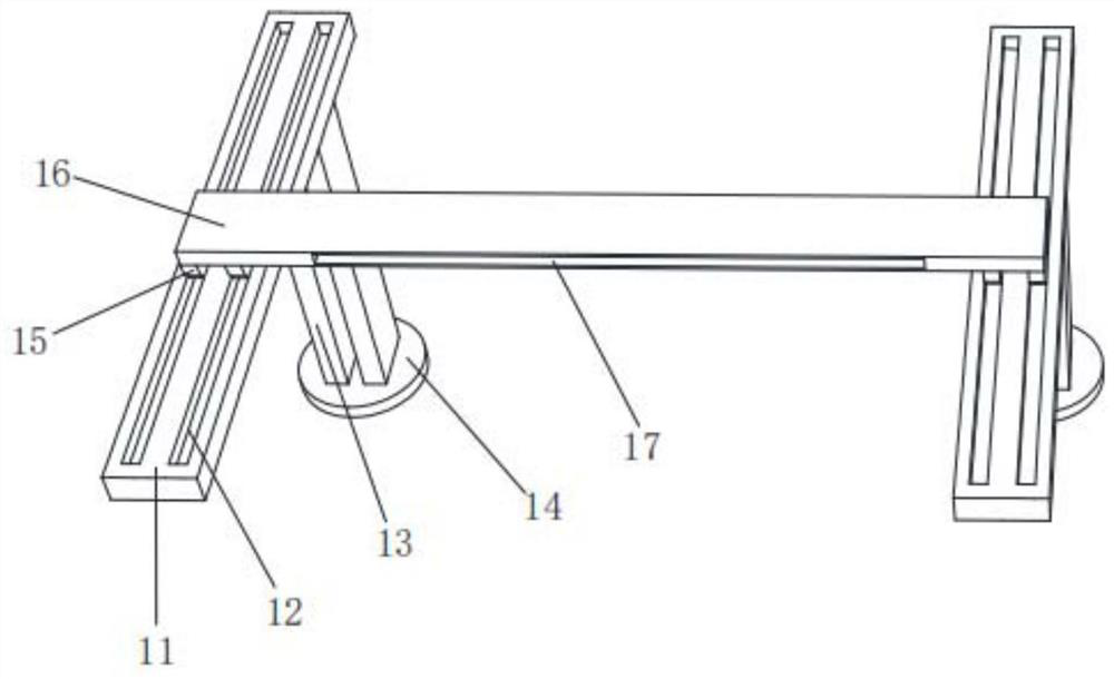
[0039] Example 1, please refer to figure 1 , image 3 , Image 6 , Figure 7 , Figure 8 with Figure 11 , the present invention provides a technical solution for crushing and separating equipment for lithium battery cell pole pieces: including fixing bars 11, two parallel chute 12 are provided on the side walls of the two fixing bars 11, and the ends of the two fixing bars 11 are fixedly installed There are support rods 13, the ends of the two support rods 13 are fixed with fixed feet 14, the side of the fixed feet 14 away from the support rods 13 is fixed with a bottom plate 101, and the ends of the bottom plate 101 are respectively fixed with a crushing box 102 and a separation box 103 And the soaking box 104, the separation box 103 is located between the crushing box 102 and the soaking box 104, the crushing box 102, the separation box 103 and the soaking box 104 are connected by two pairs of drainage plates, and the sliding block 15 is arranged in the movable inner wa...
Embodiment 2
[0047] Example 2: Please refer to Figure 9 with Figure 10 , On the basis of Embodiment 1, the end of the traction rod 45 away from the central plate 44 is movably installed with a telescopic mechanism.
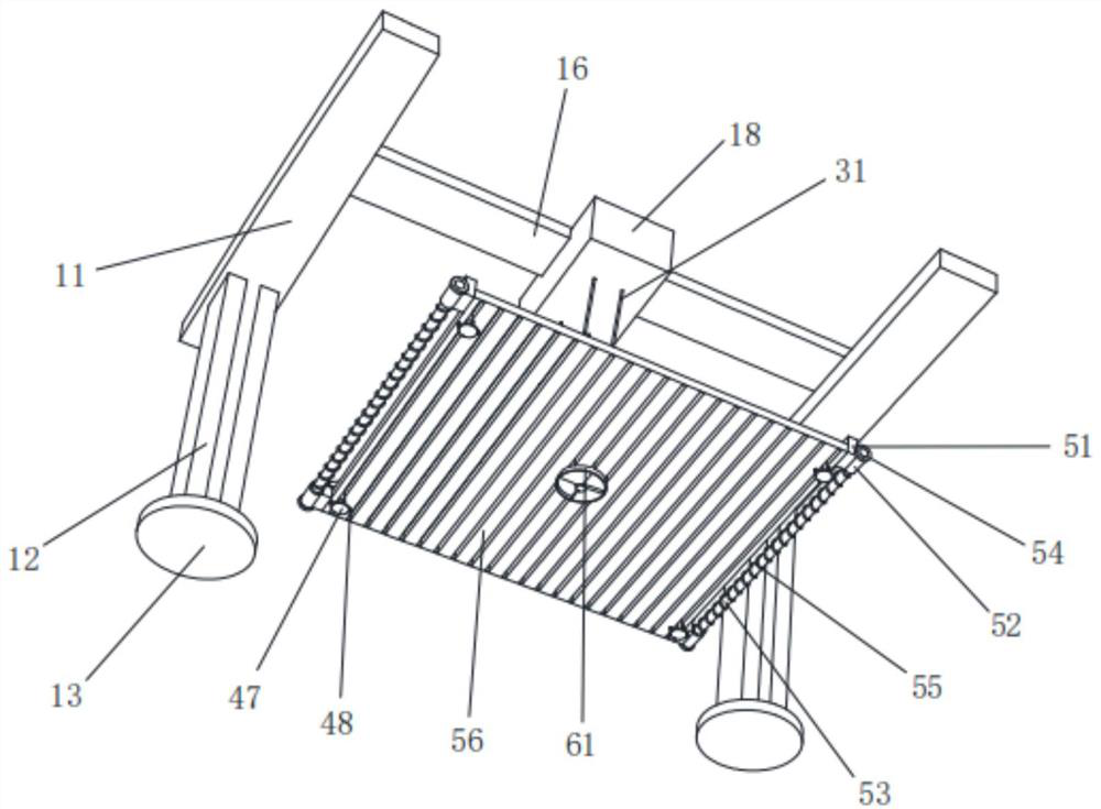
[0048] The telescoping mechanism includes a fixed block 51, which is movably installed on the side opposite to the draw bar 45. A moving sleeve 52 is fixedly installed on the side of the fixed block 51 away from the draw bar 45, and a sliding column is arranged in the side wall of the moving sleeve 52. 53, the two ends of the sliding column 53 are respectively fixedly installed with a limit plate 54, and the opposite side of the two moving sleeves 52 is fixedly installed with a spring 55, and the spring 55 is movably sleeved on the surface of the sliding column 53, and the four fixed blocks 51 are opposite to each other. That side is fixedly installed with collecting net 56.
[0049] During use, when collecting, pull the traction rope 31 through the electric hoist 18 to pu...
Embodiment 3
[0050] Example 3: Please refer to figure 2 , Figure 4 with Figure 5 , On the basis of the second embodiment, the center of the side wall of the collection net 56 is fixed with a discharge mechanism inside.
[0051] The discharge mechanism includes a discharge tray 61, the discharge tray 61 is fixedly located at the center of the side wall of the collection net 56, the inner wall of the discharge tray 61 is fixed with a fixed ring 62, and the inner wall of the fixed ring 62 is provided with an annular groove 63. The inner wall of the groove 63 is movable and provided with an arc bar 64, the opposite side of the two arc bars 64 is fixedly equipped with a turntable 65, and the opposite side of the two turntables 65 is fixedly equipped with a central column 66, and the ends of the center column 66 are fixedly installed. Turning cap 67 is arranged, and the lower end of rotating disk 65 is provided with clamping plate 68, and that face that two clamping plates 68 deviate from i...
PUM
 Abstract
Description
Claims
Application Information
 - R&D
- Intellectual Property
- Life Sciences
- Materials
- Tech Scout
- Unparalleled Data Quality
- Higher Quality Content
- 60% Fewer Hallucinations
Browse by: Latest US Patents, China's latest patents, Technical Efficacy Thesaurus, Application Domain, Technology Topic, Popular Technical Reports.
© 2025 PatSnap. All rights reserved.Legal|Privacy policy|Modern Slavery Act Transparency Statement|Sitemap|About US| Contact US: help@patsnap.com


